A rotary encoder, also called a shaft encoder, is an electro-mechanical device that converts the angular position or motion of a shaft or axle to an analog or digital signal.
There are two main types: absolute and incremental (relative). The output of absolute encoders indicates the current position of the shaft, making them angle transducers. The output of incremental encoders provides information about the motion of the shaft, which is typically further processed elsewhere into information such as speed, distance and position.
Rotary encoders are used in many applications that require precise shaft unlimited rotation—including industrial controls, robotics, special purpose photographic lenses, computer input devices (such as optomechanical mice and trackballs), controlled stress rheometers, and rotating radar platforms.
A rotary encoder is a type of position sensor which is used for determining the angular position of a rotating shaft. It generates an electrical signal, either analog or digital, according to the rotational movement.
Gambar 1.
Gambar 2.
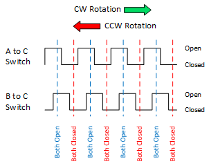
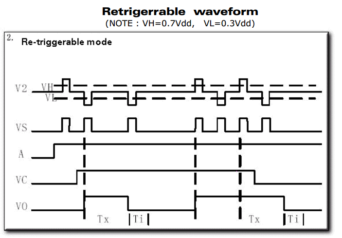
This rotary encoder is also known as quadrature encoder or relative rotary encoder and its output is a series of square wave pulses.
Incremental Encoder Quadrature Output Waveform
An incremental rotary encoder generates two output signals while its shaft is rotating which is also called quadrature ouptut. Depending on the direction, one of the signals leads the other. You can see the output signal waveforms of an incremental rotary encoder and the expected bit sequence below.
Gambar 3.
As you can see from the figure, both of the outputs stays HIGH at the initial state. When the encoder shaft starts to rotate in clockwise direction, Output A falls to LOW first and Output B follows it with a lag. In a counter-clockwise direction the operation turns opposite. Time intervals on the waveform depend on the rotation speed but the signal lagging is guaranteed in encoder operation. We will build the whole scenario on this characteristic of the incremental rotary encoder.
Mengenal Keyes KY-04 dan mencoba kode program sederhana.
 Gambar 11.
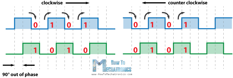 Gambar 13.
Contoh kode dari:
http://henrysbench.capnfatz.com
[code lang=”C”] int pinA = 6; // Connected to CLK on KY-040. Gantidari pin 2int pinB = 7; // Connected to DT on KY-040. Ganti dari pin 3
int encoderPosCount = 0;
int pinALast;
int aVal;
boolean bCW;
void setup() {
pinMode (pinA,INPUT);
pinMode (pinB,INPUT);
/* Read Pin A
Whatever state it’s in will reflect the last position
*/
pinALast = digitalRead(pinA);
Serial.begin (9600);
}
void loop() {
aVal = digitalRead(pinA);
if (aVal != pinALast){ // Means the knob is rotating
// if the knob is rotating, we need to determine direction
// We do that by reading pin B.
if (digitalRead(pinB) != aVal) { // Means pin A Changed first - We’re Rotating Clockwise
encoderPosCount ++;
bCW = true;
} else {// Otherwise B changed first and we’re moving CCW
bCW = false;
encoderPosCount-;
}
Serial.print (“Rotated: “);
if (bCW){
Serial.println (“clockwise”);
}else{
Serial.println(“counterclockwise”);
}
Serial.print(“Encoder Position: “);
Serial.println(encoderPosCount);
}
pinALast = aVal;
}
[/code]
Contoh kode dari:
http://howtomechatronics.com/tutorials/arduino/rotary-encoder-works-use-arduino/
[code lang=”C”] /* Arduino Rotary Encoder Tutorial*
* by Dejan Nedelkovski, www.HowToMechatronics.com
*
*/
#define outputA 6
#define outputB 7
int counter = 0;
int aState;
int aLastState;
void setup() {
pinMode (outputA,INPUT);
pinMode (outputB,INPUT);
Serial.begin (9600);
// Reads the initial state of the outputA
aLastState = digitalRead(outputA);
}
void loop() {
aState = digitalRead(outputA); // Reads the “current” state of the outputA
// If the previous and the current state of the outputA are different, that means a Pulse has occured
if (aState != aLastState){
// If the outputB state is different to the outputA state, that means the encoder is rotating clockwise
if (digitalRead(outputB) != aState) {
counter ++;
} else {
counter -;
}
Serial.print(“Position: “);
Serial.println(counter);
}
aLastState = aState; // Updates the previous state of the outputA with the current state
}
[/code]
[/su_panel] [su_panel border=”3px solid #FF6666″ radius=”20″]Description of the code: So first we need to define the pins to which our encoder is connected and define some variables needed for the program. In the setup section we need to define the two pins as inputs, start the serial communication for printing the results on the serial monitor, as well as read the initial value of the output A and put the value into the variable aLastState.
Then in the loop section we read the output A again but now we put the value into the aState variable. So if we rotate the encoder and a pulse is generated, these two values will differ and the first “if” statement will become true. Right after that using the second “if” statement we determine the rotation direction. If the output B state differ from the output A state the counter will be increased by one, else it will be decreased. At the end, after printing the results on the serial monitor, we need to update the aLastState variable with aState variable.
That’s all we need for this example. If upload the code, start the Serial Monitor and start rotating the encoder we will start getting the values in the serial monitor. The particular module that I have makes 30 counts each full cycle.
 Gambar 16.
 Gambar 17.
 Gambar 18.
 Gambar 19.
 Gambar 20.
Berikut contoh-contoh kode program, silakan membaca situs sumber aslinya untuk lebih memahami. Beberpa kode memerlukan pustaka/library yang dapat dicari melalui halaman sumber kode.
Contoh kode program dari https://github.com/PaulStoffregen/Encoder (Basic.pde)
[code lang=”C”] /** Dimodifikasi dari kode contoh:
* Encoder Library - Basic Example
* http://www.pjrc.com/teensy/td_libs_Encoder.html
*
* This example code is in the public domain.
*/
#include <Encoder.h>
// Change these two numbers to the pins connected to your encoder.
// Best Performance: both pins have interrupt capability.
// Pin 2 & pin 3 di Arduino Uno
// Good Performance: only the first pin has interrupt capability
// Low Performance: neither pin has interrupt capability
Encoder myEnc(6, 7);
// avoid using pins with LEDs attached
void setup()
{
Serial.begin(9600);
Serial.println(“Basic Encoder Test:”);
}
long oldPosition = -999;
//long oldPosition = 0;
void loop()
{
long newPosition = myEnc.read();
if (newPosition != oldPosition)
{
oldPosition = newPosition;
Serial.println(newPosition);
// Serial.println(newPosition/4);
}
}[/code]
Contoh kode program dari https://github.com/PaulStoffregen/Encoder (NoInterrupts.pde)
[code lang=”C”] /* Encoder Library - NoInterrupts Example* http://www.pjrc.com/teensy/td_libs_Encoder.html
*
* This example code is in the public domain.
*/
// If you define ENCODER_DO_NOT_USE_INTERRUPTS *before* including
// Encoder, the library will never use interrupts. This is mainly
// useful to reduce the size of the library when you are using it
// with pins that do not support interrupts. Without interrupts,
// your program must call the read() function rapidly, or risk
// missing changes in position.
#define ENCODER_DO_NOT_USE_INTERRUPTS
#include <Encoder.h>
// Beware of Serial.print() speed. Without interrupts, if you
// transmit too much data with Serial.print() it can slow your
// reading from Encoder. Arduino 1.0 has improved transmit code.
// Using the fastest baud rate also helps. Teensy has USB packet
// buffering. But all boards can experience problems if you print
// too much and fill up buffers.
// Change these two numbers to the pins connected to your encoder.
// With ENCODER_DO_NOT_USE_INTERRUPTS, no interrupts are ever
// used, even if the pin has interrupt capability
Encoder myEnc(6, 7);
// avoid using pins with LEDs attached
void setup() {
Serial.begin(9600);
Serial.println(“Basic NoInterrupts Test:”);
}
long position = -999;
void loop() {
long newPos = myEnc.read();
if (newPos != position) {
position = newPos;
Serial.println(position);
}
// With any substantial delay added, Encoder can only track
// very slow motion. You may uncomment this line to see
// how badly a delay affects your encoder.
//delay(50);
}[/code]
Contoh kode program dari https://github.com/mathertel/RotaryEncoder (InterruptRotator.ino)
[code lang=”C”] // —-// InterruptRotator.ino - Example for the RotaryEncoder library.
// This class is implemented for use with the Arduino environment.
// Copyright (c) by Matthias Hertel, http://www.mathertel.de
// This work is licensed under a BSD style license. See http://www.mathertel.de/License.aspx
// More information on: http://www.mathertel.de/Arduino
// —-
// 18.01.2014 created by Matthias Hertel
// —-
// This example checks the state of the rotary encoder in the loop() function.
// The current position is printed on output when changed.
// Hardware setup:
// Attach a rotary encoder with output pins to A2 and A3.
// The common contact should be attached to ground.
#include <RotaryEncoder.h>
// Setup a RoraryEncoder for pins A2 and A3:
RotaryEncoder encoder(A2, A3);
void setup()
{
// Serial.begin(57600);
Serial.begin(9600); //diubah
Serial.println(“SimplePollRotator example for the RotaryEncoder library.”);
// You may have to modify the next 2 lines if using other pins than A2 and A3
PCICR |= (1 << PCIE1); // This enables Pin Change Interrupt 1 that covers the Analog input pins or Port C.
PCMSK1 |= (1 << PCINT10) | (1 << PCINT11); // This enables the interrupt for pin 2 and 3 of Port C.
} // setup()
// The Interrupt Service Routine for Pin Change Interrupt 1
// This routine will only be called on any signal change on A2 and A3: exactly where we need to check.
ISR(PCINT1_vect)
{
encoder.tick(); // just call tick() to check the state.
}
// Read the current position of the encoder and print out when changed.
void loop()
{
static int pos = 0;
int newPos = encoder.getPosition();
if (pos != newPos)
{
Serial.print(newPos);
Serial.println();
pos = newPos;
// Just to show, that long lasting procedures don’t break the rotary encoder:
// When newPos is 66 the ouput will freeze, but the turned positions will be recognized even when not polled.
// The interrupt still works.
// The output is correct 6.6 seconds later.
if (newPos == 66)
{
// delay(6600);
delay(3000); //diubah
} // if newPOS
} // if
} // loop ()
// The End
[/code]

 Gambar 5. [
 Gambar 10. [
 Gambar 11. [
 Gambar 13. [
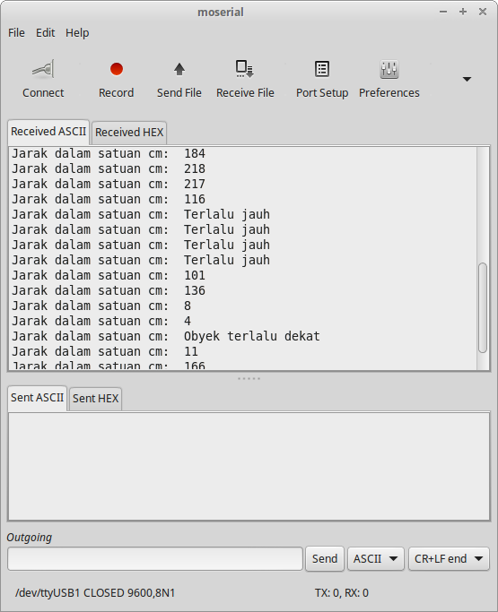 Gambar 16. Hasil pengukuran jarak
 Gambar 17.
 Gambar 19. [

 Gambar 20. [

 Gambar 21. [
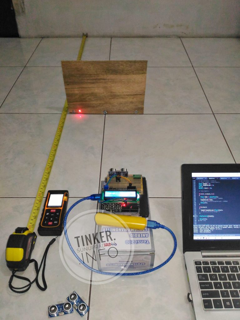
 Gambar 6. [
 Gambar 9. [
 [Gambar 10.]
 Gambar 11. [
 Gambar 2. [
 Gambar 3. [

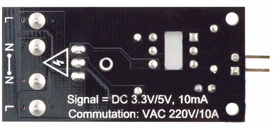
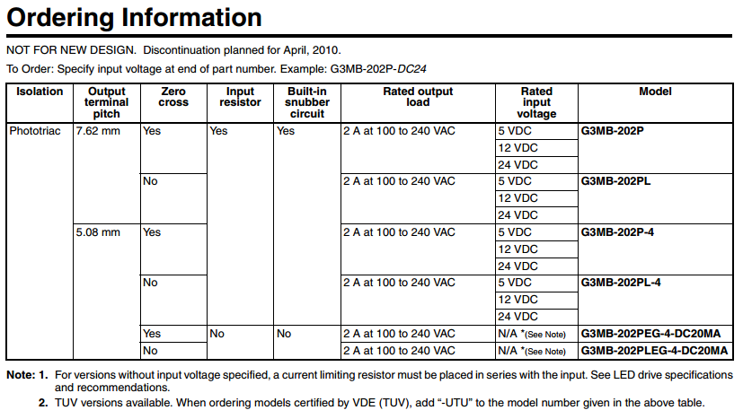
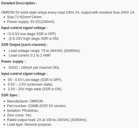 Gambar 8. Ringkasan spesifikasi papan SSR Omron G3MB [
 Gambar 9. [
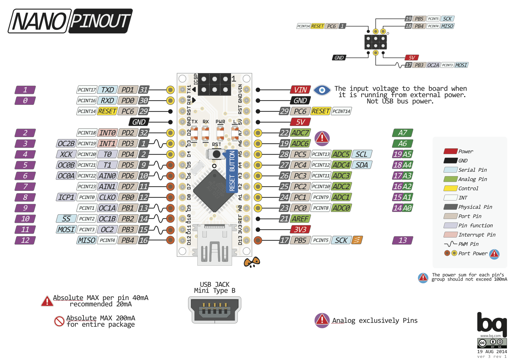
 Gambar 1.
 Gambar 3. [
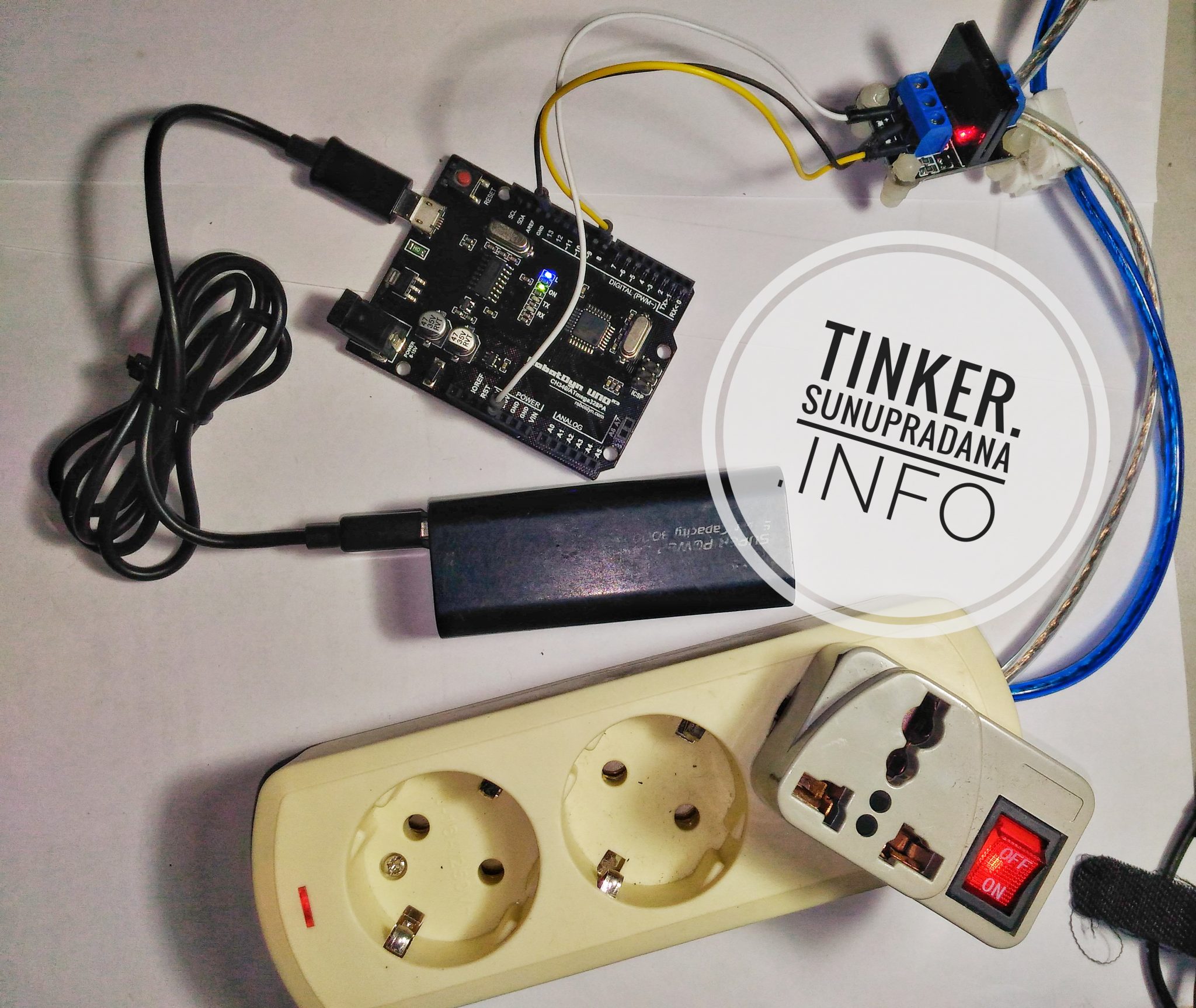
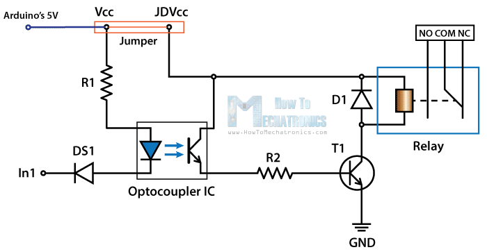 Gambar 4. Menggunakan catu daya Arduino [
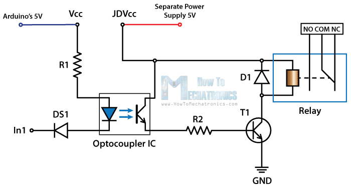 Gambar 5. Menggunakan catu daya terpisah (sambungkan juga GND) [
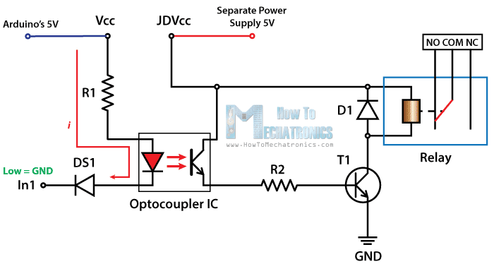 Gambar 6. Papan sistem menggunakan active-low [
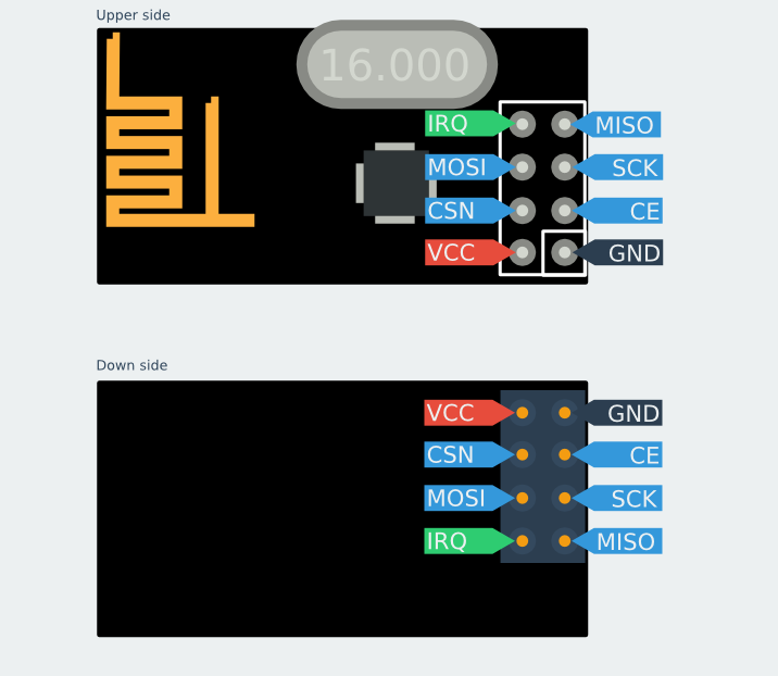 Gambar 3. nRF24L01 [
 Gambar 4.
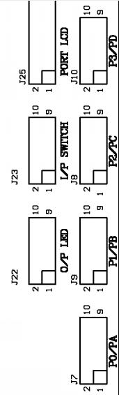 Gambar 5. Port
 Gambar 7.