1
2. APPLICATIONS
•
Domestic appliance, office machine, audio, equipment, automobile, etc. ( Remote control TV receiver, monitor display, audio equipment high rushing current use application.)
3. ORDERING INFORMATION
SRD XX VDC S L C
Model of relay Nominal coil voltage Structure Coil sensitivity Contact form A:1 form A S:Sealed type L:0.36W B:1 form B SRD 03
05
06
09
12
24
48VDC F:Flux free type
D:0.45W C:1 form C
4. RATING
CCC FILE NUMBER:CH0052885-2000 7A/240VDC CCC FILE NUMBER:CH0036746-99 10A/250VDC UL /CUL FILE NUMBER: E167996 10A/125VAC 28VDC TUV FILE NUMBER: R9933789 10A/240VAC 28VDC
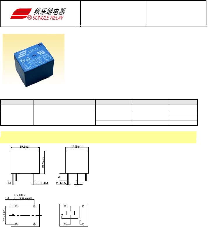
5. DIMENSION
(unit:mm)
DRILLING
(unit:mm)
WIRING DIAGRAM RELAY ISO9002
1. MAIN FEATURES
•
Switching capacity available by 10A in spite of small size design for highdensity P.C. board mounting technique.
•
UL,CUL,TUV recognized.
•
Selection of plastic material for high temperature and better chemical solution performance.
•
Sealed types available.
•
Simple relay magnetic circuit to meet low cost of mass production.
2
6. COIL DATA CHART (AT20
C)
Coil Sensitivity Coil Voltage Code Nominal Voltage (VDC) Nominal Current (mA) Coil Resistance (
Ω
)
±
10% Power Consumption (W) Pull-In Voltage (VDC) Drop-Out Voltage (VDC)
Max-Allowable Voltage (VDC)
03 03 120 25 05 05 71.4 70 06 06 60 100 09 09 40 225 12 12 30 400 24 24 15 1600 SRD (High Sensitivity) 48 48 7.5 6400 abt. 0.36W 75%Max. 10% Min.
120%
03 03 150 20 05 05 89.3 55 06 06 75 80 09 09 50 180 12 12 37.5 320 24 24 18.7 1280 abt. 0.45W SRD (Standard) 48 48 10 4500 abt. 0.51W 75% Max. 10% Min.
110%
7. CONTACT RATING
SRD Type Item FORM C FORM A Contact Capacity Resistive Load (cos
Φ
=1) 7A 28VDC 10A 125VAC 7A 240VAC 10A 28VDC 10A 240VAC Inductive Load (cos
Φ
=0.4 L/R=7msec) 3A 120VAC 3A 28VDC 5A 120VAC 5A 28VDC Max. Allowable Voltage 250VAC/110VDC 250VAC/110VDC Max. Allowable Power Force 800VAC/240W 1200VA/300W Contact Material AgCdO AgCdO
8. PERFORMANCE (at initial value)
Type Item SRD Contact Resistance 100m
Ω
Max. Operation Time 10msec Max. Release Time 5msec Max. Dielectric Strength Between coil & contact Between contacts 1500VAC 50/60HZ (1 minute) 1000VAC 50/60HZ (1 minute) Insulation Resistance 100 M
Ω
Min. (500VDC) Max. ON/OFF Switching Mechanically Electrically 300 operation/min 30 operation/min Ambient Temperature -25
°
C to +70
°
C Operating Humidity 45 to 85% RH Vibration Endurance Error Operation 10 to 55Hz Double Amplitude 1.5mm 10 to 55Hz Double Amplitude 1.5mm Shock Endurance Error Operation 100G Min. 10G Min. Life Expectancy Mechanically Electrically 10
7
operations. Min. (no load) 10
5
operations. Min. (at rated coil voltage) Weight abt. 10grs.
9.REFERENCE DATA
Coil Temperature Rise
0.10.30.50.70.00.20.40.60.851525354501020304050
Coil Power (W)
Operation Time
0.10.30.50.70.00.20.40.60.8261004812
Operation timeRelease time
Coil Power (W)
Life Expectancy
AC120V/DC24V cos
Φ
=1
261004812235235110100
Current of Load (A)
Life Expectancy
135702468235235110100
AC : 120V TV-5
Current of Load (A)