Ada banyak sumber belajar mengenai nRF24L01 di Internet, dalam berbagai format. Halaman ini hanya merangkum sebagian kecil di antaranya. Lebih lanjut silakan mengikuti link yang sudah disediakan.
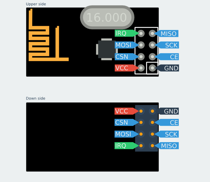
Gambar 1. nRF24L01 [sumber]
Gambar 2. nRF24L01 [sumber]
 Gambar 3. nRF24L01 [sumber]
Gambar 4. nRF24L01 [sumber]
Gambar 5. [sumber]
Gambar 6. [sumber]
Gambar 8. [sumber]
Gambar 9. [sumber]
Gambar 10. [sumber]
NOTE: These units VCC connection must go to 3.3V not 5.0V, although the Arduino itself may run at 5.0V and the signals will be OK. The NRF24L01+ IC is a 3.3V device, but its I/O pins are 5 V tolerant , which makes it easier to interface to Arduino/YourDuino.
Arduino UNO and earlier versions have a 3.3V output that can run the low-power version of these modules (See Power Problems at the top of this page!), but the high-power versions must have a separate 3.3V supply or use a Base Module with a 3.3V regulator. The YourDuino RoboRED has a higher power 3.3V regulator and can be used to run the high-power Power Amplifier type module without a separate 3.3V regulator. ~arduino-info.wikispaces.com
[/su_panel] [su_panel border=”3px solid #30C0F0″ radius=”10″]If you scroll through the RF24 library documentation, you will notice that there are many parameters that can be set. Some key parameters are
- Channel: the specific frequency channel that communication will occur on (frequencies are mapped to integers between 0 and 125
- Reading pipe: the reading pipe is a unique 24, 32, or 40-bit address from which the module reads data
- Writing pipe: the writing pipe is a unique address to which the module writes data
- Power Amplifier (PA) level: the PA level sets the power draw of the chip and thereby the transmission power. For the purposes of this tutorial (use with the Arduino) we will use the minimum power setting.
The RF24 library documentation page provides some great example code for getting started with the library. The example projects can be found here: http://tmrh20.github.io/RF24/examples.html ~DevicePlus
Keseluruhan dari keterangan dalam kotak ini dikutip dari
https://arduino-info.wikispaces.com/Nrf24L01-2.4GHz-HowTo :
RF24 LIBRARIES: Commonly Used Commands (Methods):
NOTE: If you wish, see ALL the details HERE.
We will try to understand the commands to set up and operate an nRF24L01 radio and build a very simple working example.
First we will look at the minimum needed to set up and transmit or receive data. Later we will write more complete examples and get them working with real radios..
CREATE AND START UP A RADIO (For either transmit or receive):
RF24 (uint8_t _cepin, uint8_t _cspin) Create a radio and set the Arduino pins to be used for CE and CS)
EXAMPLE: (Create an instance of a radio, specifying the CE and CS pins. )
RF24 myRadio (7,8); “myRadio” is the identifier you will use in the following examples
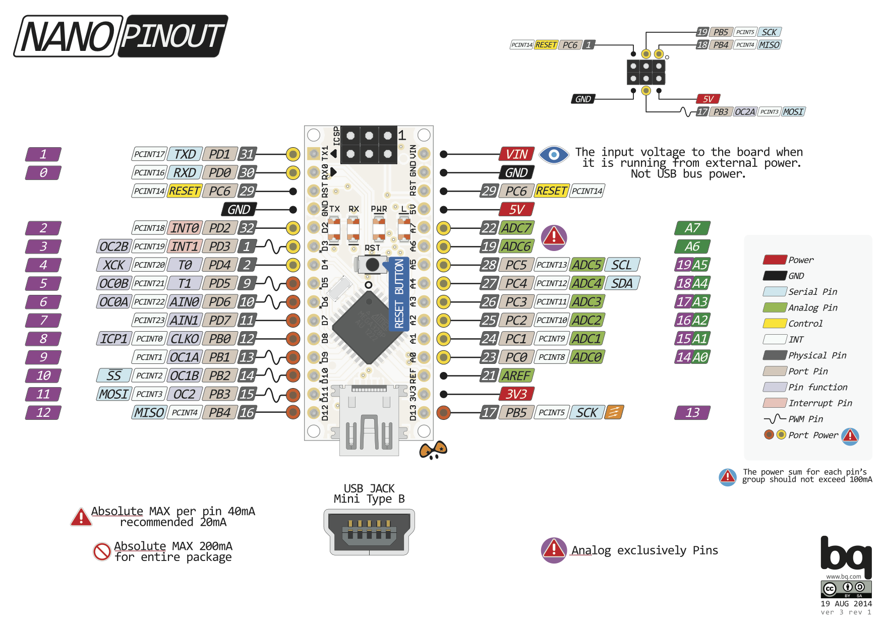
NOTE: The following pins are fixed and unchangeable. AND Vcc (supply voltage MUST be 3.3V)
SCK to Arduino pin 13
MOSI to Arduino pin 11
MISO to Arduino pin 12
NOTE: In all following commands, you must use the same identifying name you used in the RF24 statement that created the radio. (“myRadio” in the example above) You will use that identifier followed by (dot) followed by the method (command), followed by parameters. This is “object oriented programming”. The OBJECT in this case is the Radio, and there are many METHODS that can operate on the Object. A METHOD is much like a Function or a Subroutine.
EXAMPLE: myRadio.begin(); Start up the actual radio module with the “begin” method
NOTE: “PIPES” : This is often confusing. nRF24L01 uses “pipes” that connect from transmitter to receiver. Pipes have an address you need to set. The Transmitter pipe must have the same address as the Receiver pipe. Later it’s possible to use multiple “pipes” at once
EXAMPLE OF RECEIVING DATA:
myRadio.openReadingPipe (1, const uint8_t *address) Pipe number (usually 1), pipe address (which is usually 5 bytes in an array structure).
EXAMPLE:
byte addresses[][6] = {“1Node”}; Create address for 1 pipe.
myRadio.openReadingPipe(1, addresses[0]); Use the first entry in array ‘addresses’ (Only 1 right now)
myRadio.startListening (); Turn on the receiver and listen for received data. You MUST have opened a reading pipe FIRST.
if( myRadio.available()) Check for available incoming data from transmitter
{
while (myRadio.available()) While there is data ready
{
myRadio.read( &myData, sizeof(myData) ) ; Get the data payload (You must have defined that already!)
}
myRadio.stopListening(); stop listening
EXAMPLE OF TRANSMITTING DATA:
byte addresses[][6] = {“1Node”}; Create address for 1 pipe.
myRadio.openWritingPipe(1, addresses[0]); Use the first entry in array ‘addresses’ (Only 1 right now)
myRadio.write( &myData, sizeof(myData) )
We have written working examples of Transmit and Receive sketches using these methods. See them HERE
SET SOME OTHER OPERATING OPTIONS AND PARAMETERS:
NOTE: Many of these methods have default values you can usually use.
radio.printDetails();
Prints out a LOT of debugging information.
radio.setDataRate(RF24_250KBPS);
speed RF24_250KBPS for 250kbs, RF24_1MBPS for 1Mbps, or RF24_2MBPS for 2Mbps. 250K Bits per second gives longest range.
radio.setPALevel(RF24_PA_MAX);
Set Power Amplifier (PA) level to one of four levels: RF24_PA_MIN, RF24_PA_LOW, RF24_PA_HIGH and RF24_PA_MAX
The power levels correspond to the following output levels respectively: NRF24L01: -18dBm, -12dBm,-6dBM, and 0dBm
0 dBm is equal to 1 milliwatt. Each 3 dB is a 2:1 ratio. 6 dB is 4:1 10 dB is 10:1 So -18 dBm is 0.0000158489 watts !
To calculate all this dBm Stuff (Which us old Radio Engineers love) See THIS..
The “High Power” nRF24L01 modules like THIS have a gain of 100, so their output is +20 dBm (100 milliwatts)
radio.setChannel(108);
Which RF channel to communicate on, 0-124 Can operate on frequencies from 2.400GHz to 2.524GHz.
Programming resolution of channel frequency is 1Mhz
This is the same unlicensed band WiFi operates in (WiFi uses 2.400 to 2.500 gHz). Usually frequencies above channel 100 are best.
NOTE: In most countries the allowed frequencies are from 2.400GHz to 2.483.5GHz which you must not exceed. In USA it’s best to use channels from 70 to 80.
You can scan the channels in your environment to find a channel that is clear… See this Scanner sketch.
radio.enableDynamicPayloads();
Enable custom length payloads on the acknowledge packets. Ack payloads are a handy way to return data back to senders without manually changing the radio modes on both units.
radio.setRetries(15,15);
Set the number and delay of retries upon failed transmit. Parameters:
delay: How long to wait between each retry, in multiples of 250us, max is 15. 0 means 250us, 15 means 4000us.
count: How many retries before giving up, max 15
radio.setCRCLength(RF24_CRC_16);
length: RF24_CRC_8 for 8-bit or RF24_CRC_16 for 16-bit Cyclic Redundancy Check (Error checking)
[/su_panel] [su_panel border=”3px solid #FF6666″ radius=”10″] [/su_panel] [su_panel border=”3px solid #00C700″ radius=”10″]
Gambar 12.
Gambar 13.
Gambar 14. [sumber]
 Gambar 15.
 Gambar 16.
Kode uji pengiriman sederhana #01. Sender :
#include <SPI.h>
#include <nRF24L01.h>
#include <RF24.h>
// uint8_t sVal = 0;
RF24 myRadio(9, 10);
byte addresses[][6] = {"1Nodx"}; // Create address for 1 pipe.
// const uint64_t pipe = 0xE8E8F0F0E1LL;
void setup(void)
{
  delay(2000);
  myRadio.begin();
  myRadio.setChannel(108);  // Above most Wifi Channels
  myRadio.setPALevel(RF24_PA_MIN);
  myRadio.openWritingPipe( addresses[0]); // Use the first entry in array 'addresses' (Only 1 right now)
  // radio.openWritingPipe(pipe);
}
void loop(void)
{
  for(int i=0; i<100; i++)
  {
    // myRadio.write(&sVal, sizeof(sVal));
    myRadio.write(&i, sizeof(i));
    delay(400);
  }
}
Kode uji pengiriman sederhana #01. Receiver :
#include <SPI.h>
#include <nRF24L01.h>
#include <RF24.h>
#include <Wire.h>
#include <LCD.h>
#include <LiquidCrystal_I2C.h>
LiquidCrystal_I2C lcd(0x3F, 2, 1, 0, 4, 5, 6, 7, 3, POSITIVE);
// Addr, En, Rw, Rs, d4, d5, d6, d7, backlighpin, polarity
RF24 myRadio(9, 10);
byte addresses[][6] = {"1Node"}; // Create address for 1 pipe.
// const uint64_t pipe = 0xE8E8F0F0E1LL;
int nilaiTerkirim;
void setup(void)
{
  lcd.off();
  Serial.begin(115200);
  myRadio.begin();
  myRadio.setChannel(108);  // Above most Wifi Channels
  myRadio.setPALevel(RF24_PA_MIN);
  myRadio.openReadingPipe(1, addresses[0]); // Use the first entry in array 'addresses' (Only 1 right now)
  // radio.openReadingPipe(1, pipe);
  myRadio.startListening();
  lcd.on();
  lcd.begin(16, 2);
  lcd.backlight();
  lcd.clear();
  lcd.print("Uji nRF24L01 ...");
  delay(1000);
  lcd.clear();
  lcd.print("Starting ...");
  delay(2000);
  lcd.clear();
}
void loop(void)
{
  if ( myRadio.available() )
  {
    while (myRadio.available())
    {
      myRadio.read(&nilaiTerkirim, sizeof(nilaiTerkirim));
//      lcd.clear();
//      delay(500);
      lcd.setCursor(0, 0);
      lcd.print("Nilai: ");
      lcd.print(nilaiTerkirim);
      delay(400);
    }
  }
  else
  {
    lcd.setCursor(0, 0);
    lcd.print("No radio");
    delay(1000);
  }
//  delay(200);
  lcd.clear();
}
Kode dimodifikasi dari:
- http://www.elec-cafe.com/arduino-wireless-temperature-lcd-display-nrf24l01-dht11/
- https://arduino-info.wikispaces.com/Nrf24L01-2.4GHz-ExampleSketches#bm1
Kode uji pengiriman sederhana #02. Sender :
/*
	M O D I F I E D code
  Beberapa bagian kode di bawah ini telah diubah.
  Untuk melihat kode aslinya silakan membuka situs asal.
	YourDuinoStarter Example: Simple nRF24L01 Transmit
  - WHAT IT DOES: Transmits simple fixed data with nRF24L01 radio
  - SEE the comments after "//" on each line below
   Start with radios about 4 feet apart.
  - SEE the comments after "//" on each line below
  - CONNECTIONS: nRF24L01 Modules See:
  http://arduino-info.wikispaces.com/Nrf24L01-2.4GHz-HowTo
  Uses the RF24 Library by TMRH2o here:
  https://github.com/TMRh20/RF24
   1 - GND
   2 - VCC 3.3V !!! NOT 5V
   3 - CE to Arduino pin 9 //Telah diubah
   4 - CSN to Arduino pin 10 //Telah diubah
   5 - SCK to Arduino pin 13
   6 - MOSI to Arduino pin 11
   7 - MISO to Arduino pin 12
   8 - UNUSED
   V1.02 02/06/2016
   Questions: [email protected] */
/*-----( Import needed libraries )-----*/
#include <SPI.h>   // Comes with Arduino IDE
#include "RF24.h"  // Download and Install (See above)
/*-----( Declare Constants and Pin Numbers )-----*/
/*-----( Declare objects )-----*/
// (Create an instance of a radio, specifying the CE and CS pins. )
RF24 myRadio (9, 10); // "myRadio" is the identifier you will use in following methods
/*-----( Declare Variables )-----*/
byte addresses[][6] = {"1Node"}; // Create address for 1 pipe.
int dataTransmitted;  // Data that will be Transmitted from the transmitter
void setup()   /****** SETUP: RUNS ONCE ******/
{
  // Use the serial Monitor (Symbol on far right). Set speed to 115200 (Bottom Right)
  Serial.begin(115200);
  delay(1000);
  Serial.println(F("RF24/Simple Transmit data Test"));
  // Serial.println(F("Questions: [email protected]"));
  Serial.println(F("Questions: RTFM"));
  dataTransmitted = 10; // Arbitrary known data to transmit. Change it to test...
  myRadio.begin();  // Start up the physical nRF24L01 Radio
  myRadio.setChannel(108);  // Above most Wifi Channels
  // Set the PA Level low to prevent power supply related issues since this is a
  // getting_started sketch, and the likelihood of close proximity of the devices. RF24_PA_MAX is default.
  myRadio.setPALevel(RF24_PA_MIN);
  //  myRadio.setPALevel(RF24_PA_MAX);  // Uncomment for more power
  myRadio.openWritingPipe( addresses[0]); // Use the first entry in array 'addresses' (Only 1 right now)
  delay(1000);
}//--(end setup )---
void loop()   /****** LOOP: RUNS CONSTANTLY ******/
{
  myRadio.write( &dataTransmitted, sizeof(dataTransmitted) ); //  Transmit the data
  Serial.print(F("Data Transmitted = "));
  Serial.print(dataTransmitted);
  Serial.println(F(" No Acknowledge expected"));
  dataTransmitted = dataTransmitted + 1;  // Send different data next time
  delay(500);
}//--(end main loop )---
/*-----( Declare User-written Functions )-----*/
//*********( THE END )***********
Kode uji pengiriman sederhana #02. Receiver :
/*
  Beberapa bagian kode di bawah ini telah diubah.
  Untuk melihat kode aslinya silakan membuka situs asal.
  YourDuinoStarter Example: Simple nRF24L01 Receive
  - WHAT IT DOES: Receives simple fixed data with nRF24L01 radio
  - SEE the comments after "//" on each line below
   Start with radios about 4 feet apart.
  - SEE the comments after "//" on each line below
  - CONNECTIONS: nRF24L01 Modules See:
  http://arduino-info.wikispaces.com/Nrf24L01-2.4GHz-HowTo
  Uses the RF24 Library by TMRH2o here:
  https://github.com/TMRh20/RF24
   1 - GND
   2 - VCC 3.3V !!! NOT 5V
   3 - CE to Arduino pin 9 //Telah diubah
   4 - CSN to Arduino pin 10 //Telah diubah
   5 - SCK to Arduino pin 13
   6 - MOSI to Arduino pin 11
   7 - MISO to Arduino pin 12
   8 - UNUSED
   V1.02 02/06/2016
   Questions: [email protected] */
/*-----( Import needed libraries )-----*/
#include <SPI.h>   // Comes with Arduino IDE
#include "RF24.h"  // Download and Install (See above)
#include <LiquidCrystal_I2C.h>
/*-----( Declare Constants and Pin Numbers )-----*/
//None yet
/*-----( Declare objects )-----*/
// (Create an instance of a radio, specifying the CE and CS pins. )
RF24 myRadio (9, 10); // "myRadio" is the identifier you will use in following methods
LiquidCrystal_I2C lcd(0x3F, 2, 1, 0, 4, 5, 6, 7, 3, POSITIVE);
// Addr, En, Rw, Rs, d4, d5, d6, d7, backlighpin, polarity
/*-----( Declare Variables )-----*/
byte addresses[][6] = {"1Node"}; // Create address for 1 pipe.
int dataReceived;  // Data that will be received from the transmitter
void setup()   /****** SETUP: RUNS ONCE ******/
{
  delay(100);
  // Use the serial Monitor (Symbol on far right). Set speed to 115200 (Bottom Right)
  Serial.begin(115200);
  delay(100);
  Serial.println(F("RF24/Simple Receive data Test"));
  Serial.println(F("Q: RTFM dude"));
  myRadio.begin();  // Start up the physical nRF24L01 Radio
  myRadio.setChannel(108);  // Above most Wifi Channels
  // Set the PA Level low to prevent power supply related issues since this is a
  // getting_started sketch, and the likelihood of close proximity of the devices. RF24_PA_MAX is default.
  myRadio.setPALevel(RF24_PA_MIN);
  //  myRadio.setPALevel(RF24_PA_MAX);  // Uncomment for more power
  myRadio.openReadingPipe(1, addresses[0]); // Use the first entry in array 'addresses' (Only 1 right now)
  myRadio.startListening();
  delay(200);
  lcdInit();
}//--(end setup )---
void loop()   /****** LOOP: RUNS CONSTANTLY ******/
{
//  lcd.clear();
  if ( myRadio.available()) // Check for incoming data from transmitter
  {
    while (myRadio.available())  // While there is data ready
    {
      myRadio.read( &dataReceived, sizeof(dataReceived) ); // Get the data payload (You must have defined that already!)
    }
    // DO something with the data, like print it
    Serial.print("Data received = ");
    Serial.println(dataReceived);
    lcdDisp(dataReceived);
  } //END Radio available
  else
  {
    lcd.clear();
    // lcd.setCursor(0, 0);
    lcd.print("No radio");
    delay(1000);
    lcd.clear();
  }
}//--(end main loop )---
/*-----( Declare User-written Functions )-----*/
void lcdInit()
{
  lcd.begin(16, 2);
  lcd.backlight();
  lcd.clear();
  lcd.print("Uji nRF24L01 ...");
  delay(1000);
  lcd.clear();
  lcd.print("Mulai ...");
  delay(2000);
  lcd.clear();
}
void lcdDisp(int dataIN)
{
  lcd.setCursor(0, 0);
  lcd.print("Nilai: ");
  lcd.print(dataIN);
  delay(500);
}
//None yet
//*********( THE END )***********
Gambar 17.
Kode dimodifikasi dari:
- http://www.elec-cafe.com/arduino-wireless-temperature-lcd-display-nrf24l01-dht11/
- https://arduino-info.wikispaces.com/Nrf24L01-2.4GHz-ExampleSketches#bm1