[ [ images & links ] ]
[su_panel border=”3px solid #FFCC00″ radius=”10″]
Gambar 1. [sumber]
Gambar 2. [sumber]
Gambar 3. [sumber]
 Gambar 4. [sumber]
 Gambar 5. [sumber]
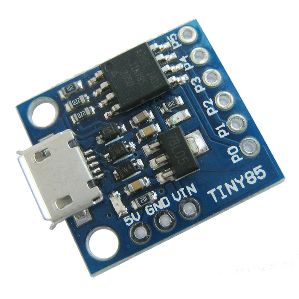
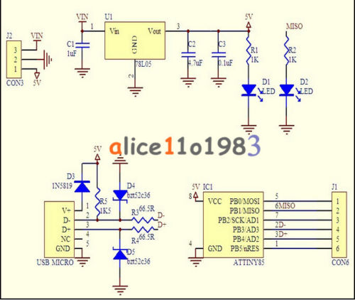
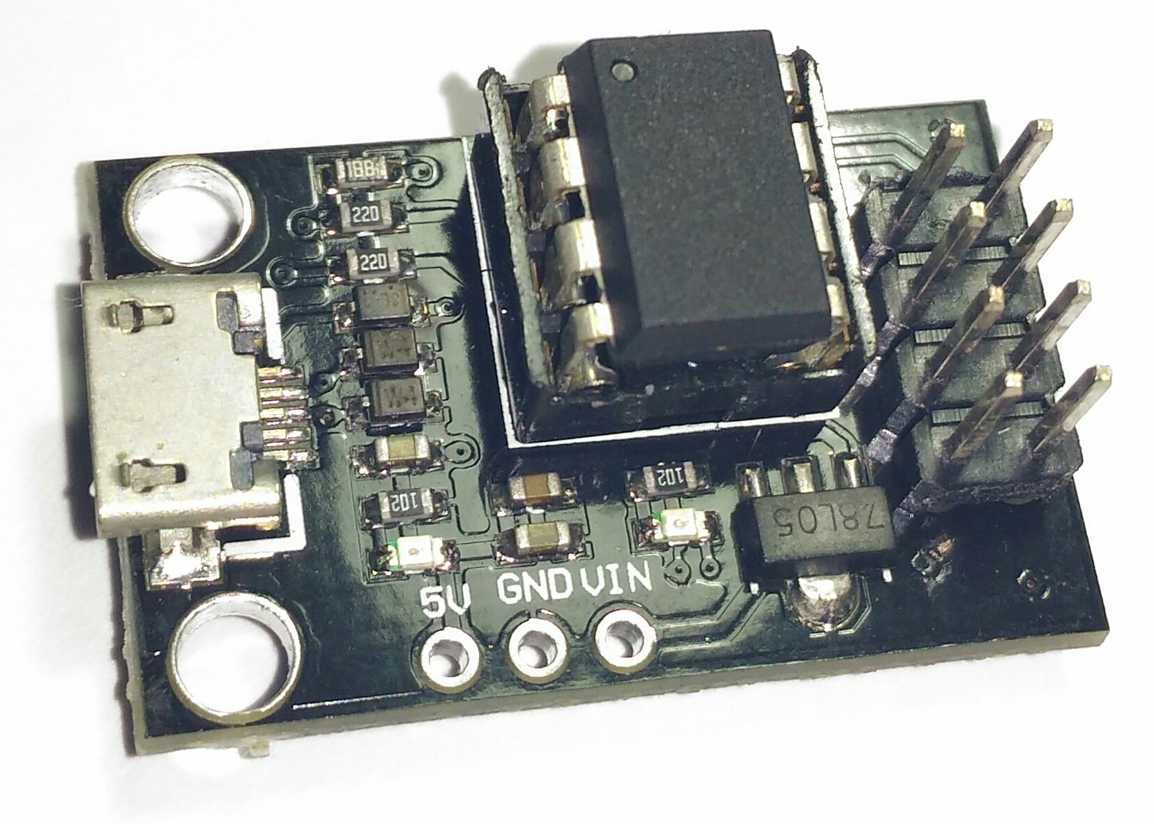
Pin outs:
-
All pins can be used as Digital I/O
-
Pin 0 → I2C SDA, PWM (LED on Model B)
-
Pin 1 → PWM (LED on Model A)
-
Pin 2 → I2C SCK, Analog In
-
Pin 3 → Analog In (also used for USB+ when USB is in use)
-
Pin 4 → PWM, Analog (also used for USB- when USB is in use)
-
Pin 5 → Analog In
 Gambar 6.
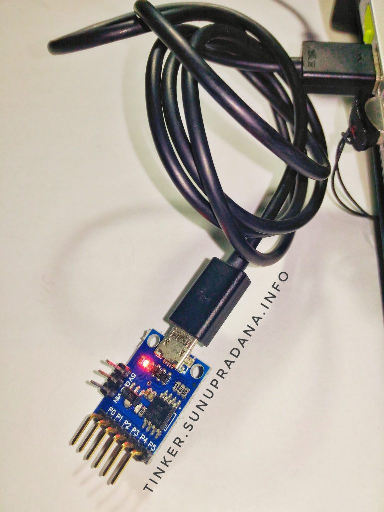 Gambar 7.
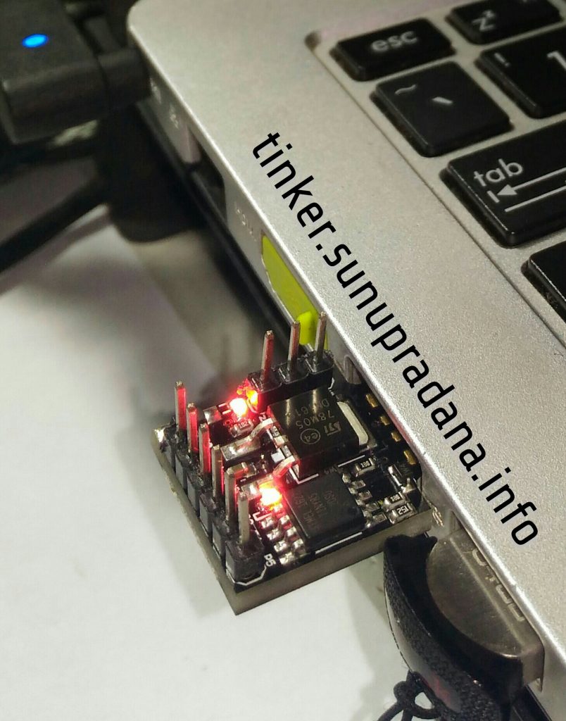
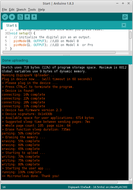
As opposed to most arduinos, to upload a new program to the device this should not be connected to the USB port. With the device unpluggled click on upload in the Arduino IDE and then connect the device to the USB port. The system will automatically detect it and upload the code.
[/su_panel]
[su_panel border=”3px solid #30C0F0″ radius=”10″]
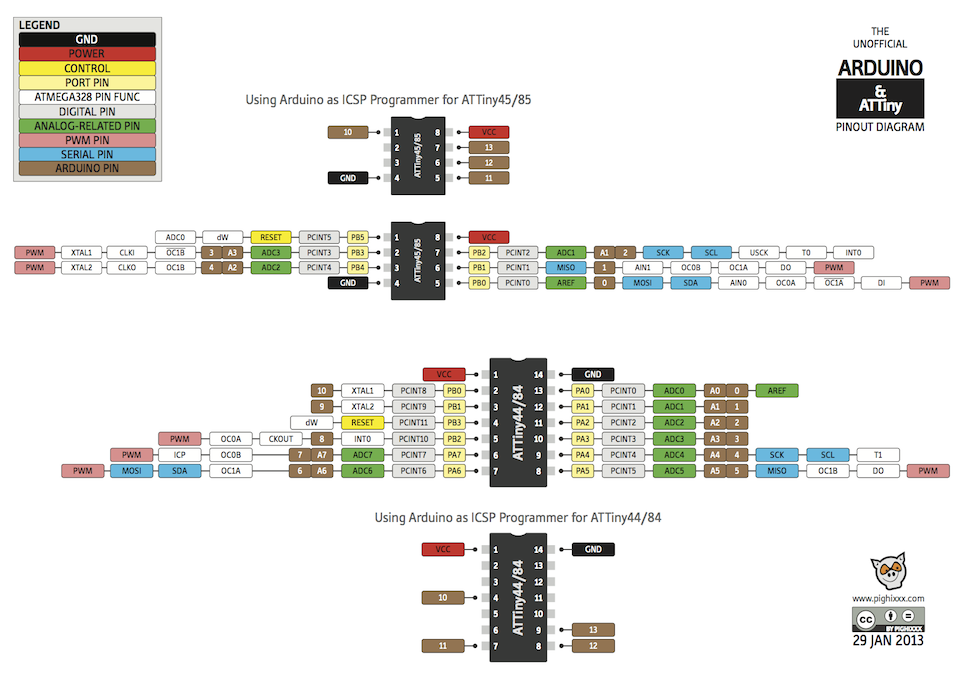
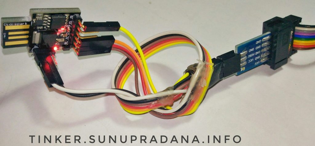 Gambar 8. Koneksi dengan USBasp
Gambar 9.
Gambar 10.
[/su_panel]
[su_panel border=”3px solid #FF6666″ radius=”10″]
Gambar 11.
 Gambar 12. Jika menggunakan “t85_aggressive.hex”, pemrograman berlangsung otomatis
// the setup routine runs once when you press reset:
void setup() {
  // initialize the digital pin as an output.
  pinMode(0, OUTPUT); //LED on Model B
  pinMode(1, OUTPUT); //LED on Model A  or Pro
}
// the loop routine runs over and over again forever:
void loop() {
  digitalWrite(0, HIGH);   // turn the LED on (HIGH is the voltage level)
  digitalWrite(1, HIGH);
  delay(400);               // wait for a second
  digitalWrite(0, LOW);    // turn the LED off by making the voltage LOW
  digitalWrite(1, LOW);
  delay(400);               // wait for a second
}
[/su_panel]
[su_panel border=”3px solid #990066″ radius=”10″]
If you are running GNU/Linux and getting errors on upload or other strange results you might need to add the USB device to udev. You must place the udev rules below into a file named /etc/udev/rules.d/49-micronucleus.rules
Create the /etc/udev/rules.d/49-micronucleus.rules file with this content (setting up the correct permissions for user and group if desired):
# UDEV Rules for Micronucleus boards including the Digispark.
# This file must be placed at:
#
# /etc/udev/rules.d/49-micronucleus.rules    (preferred location)
#   or
# /lib/udev/rules.d/49-micronucleus.rules    (req'd on some broken systems)
#
# After this file is copied, physically unplug and reconnect the board.
#
SUBSYSTEMS=="usb", ATTRS{idVendor}=="16d0", ATTRS{idProduct}=="0753", MODE:="0666"
KERNEL=="ttyACM*", ATTRS{idVendor}=="16d0", ATTRS{idProduct}=="0753", MODE:="0666", ENV{ID_MM_DEVICE_IGNORE}="1"
#
# If you share your linux system with other users, or just don't like the
# idea of write permission for everybody, you can replace MODE:="0666" with
# OWNER:="yourusername" to create the device owned by you, or with
# GROUP:="somegroupname" and mange access using standard unix groups.
Then restart the system or run this command to apply the rules:
udevadm control --reload-rules
[/su_panel]
 Gambar 1.
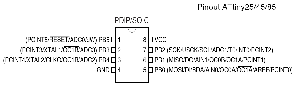 Gambar 3.
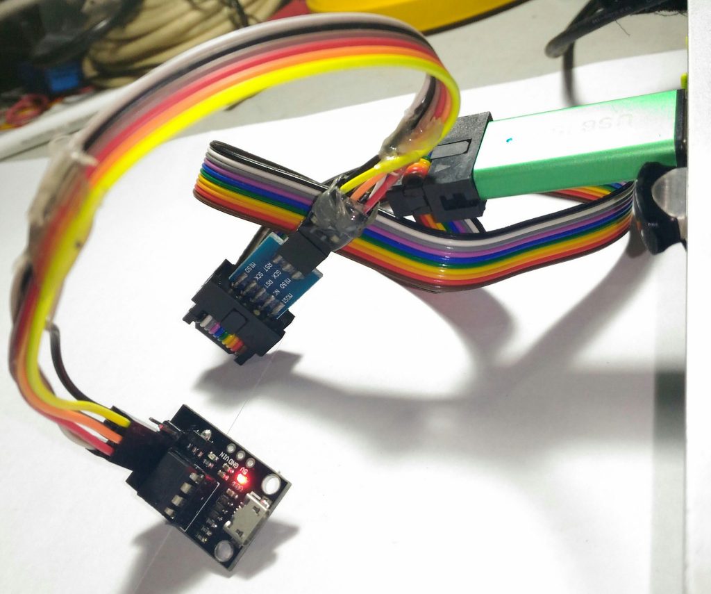 Gambar 4.
 Gambar 7.
 Gambar 8.
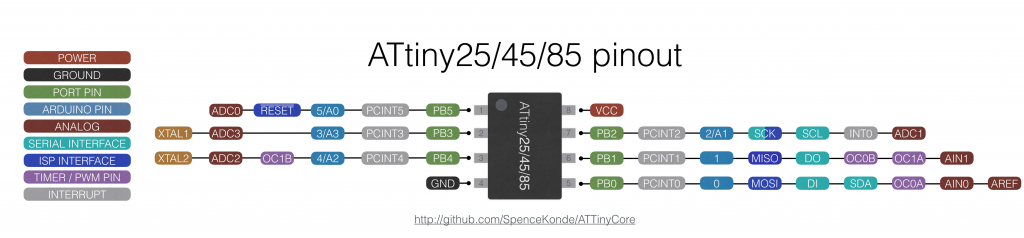 Gambar 14. [sumber]
 Gambar 15.