https://learn.adafruit.com/adafruit-data-logger-shield?view=all :
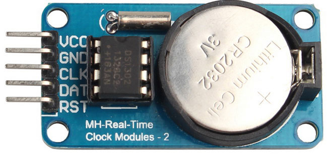
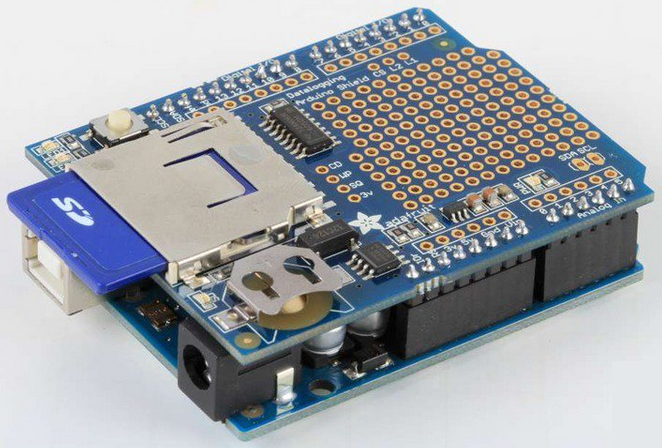 Gambar 1. learn.adafruit.com
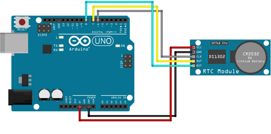
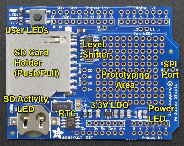 Gambar 2.
Place the SD library folder your sketchbook libraries folder. You may need to create the libraries subfolder if its your first library.
https://learn.adafruit.com/adafruit-data-logger-shield?view=all :
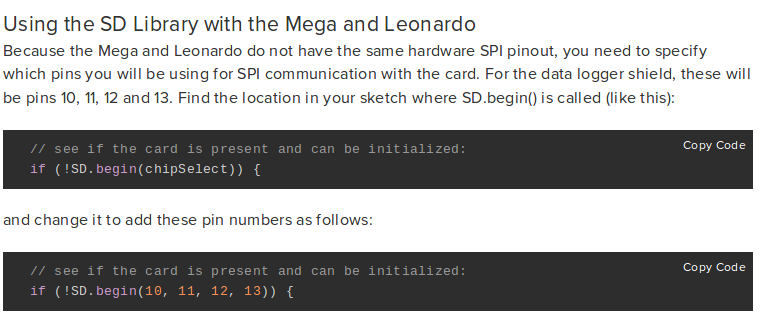
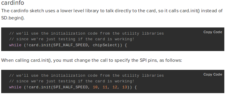
 Gambar 3.
Adafruit library examples.
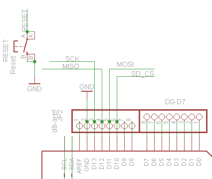
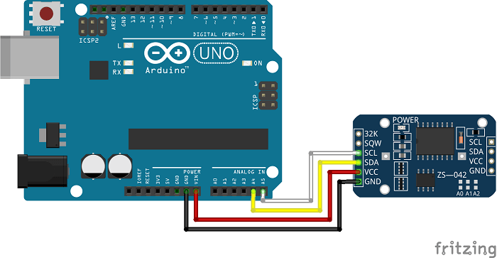
Deek-Robot: Data logging shield V1.0
D10 - Chip Select
D11 - SPI MOSI
D12 - SPI MISO
D13 - SPI SCK
// for the data logging shield, we use digital pin 10 for the SD cs line
const int chipSelect = 10;
// the logging file
File logfile;
void error(char *str)
{
Serial.print("error: ");
Serial.println(str);
// red LED indicates error
digitalWrite(redLEDpin, HIGH);
while(1);
}
[/code]
“Next is the error() function, which is just a shortcut for us, we use it when something Really Bad happened, like we couldn’t write to the SD card or open it. It prints out the error to the Serial Monitor, turns on the red error LED, and then sits in a while(1); loop forever, also known as a halt“
Serial.print("Initializing SD card…");
// make sure that the default chip select pin is set to
// output, even if you don’t use it:
pinMode(10, OUTPUT);
// see if the card is present and can be initialized:
if (!SD.begin(chipSelect)) {
Serial.println("Card failed, or not present");
// don’t do anything more:
return;
}
Serial.println("card initialized.");
// create a new file
char filename[] = "LOGGER00.CSV";
for (uint8_t i = 0; i < 100; i++) {
filename[6] = i/10 + ‘0’;
filename[7] = i%10 + ‘0’;
if (! SD.exists(filename)) {
// only open a new file if it doesn’t exist
logfile = SD.open(filename, FILE_WRITE);
break; // leave the loop!
}
}
if (! logfile) {
error("couldnt create file");
}
Serial.print("Logging to: ");
Serial.println(filename);
[/code]
“Now the code starts to talk to the SD card, it tries to initialize the card and find a FAT16/FAT32 partition. Next it will try to make a logfile. We do a little tricky thing here, we basically want the files to be called something like LOGGERnn.csv where nn is a number. By starting out trying to create LOGGER00.CSV and incrementing every time when the file already exists, until we get to LOGGER99.csv, we basically make a new file every time the Arduino starts up To create a file, we use some Unix style command flags which you can see in the logfile.open() procedure. FILE_WRITE means to create the file and write data to it. Assuming we managed to create a file successfully, we print out the name to the Serial port.”
[code lang=”C”] Wire.begin();if (!RTC.begin()) {
logfile.println("RTC failed");
#if ECHO_TO_SERIAL
Serial.println("RTC failed");
#endif //ECHO_TO_SERIAL
}
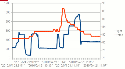
logfile.println("millis,time,light,temp");
#if ECHO_TO_SERIAL
Serial.println("millis,time,light,temp");
#if ECHO_TO_SERIAL// attempt to write out the header to the file
if (logfile.writeError || !logfile.sync()) {
error("write header");
}
pinMode(redLEDpin, OUTPUT);
pinMode(greenLEDpin, OUTPUT);
// If you want to set the aref to something other than 5v
//analogReference(EXTERNAL);
}
[/code]
“OK we’re wrapping up here. Now we kick off the RTC by initializing the Wire library and poking the RTC to see if its alive. Then we print the header. The header is the first line of the file and helps your spreadsheet or math program identify whats coming up next. The data is in CSV (comma separated value) format so the header is too: “millis,time,light,temp” the first item millis is milliseconds since the Arduino started, time is the time and date from the RTC, light is the data from the CdS cell and temp is the temperature read. You’ll notice that right after each call to logfile.print() we have #if ECHO_TO_SERIAL and a matching Serial.print() call followed by a #if ECHO_TO_SERIAL this is that debugging output we mentioned earlier. The logfile.print() call is what writes data to our file on the SD card, it works pretty much the same as the Serial version. If you set ECHO_TO_SERIAL to be 0 up top, you won’t see the written data printed to the Serial terminal. Finally, we set the two LED pins to be outputs so we can use them to communicate with the user. There is a commented-out line where we set the analog reference voltage. This code assumes that you will be using the ‘default’ reference which is the VCC voltage for the chip - on a classic Arduino this is 5.0V. You can get better precision sometimes by lowering the reference. However we’re going to keep this simple for now! Later on, you may want to experiment with it.”
Main loop
Now we’re onto the loop, the loop basically does the following over and over:
- Wait until its time for the next reading (say once a second - depends on what we defined)
- Ask for the current time and date froom the RTC
- Log the time and date to the SD card
- Read the photocell and temperature sensor
- Log those readings to the SD card
- Sync data to the card if its time
{
DateTime now;
// delay for the amount of time we want between readings
delay((LOG_INTERVAL -1) - (millis() % LOG_INTERVAL));
digitalWrite(greenLEDpin, HIGH);
// log milliseconds since starting
uint32_t m = millis();
logfile.print(m); // milliseconds since start
logfile.print(", ");
#if ECHO_TO_SERIAL
Serial.print(m); // milliseconds since start
Serial.print(", ");
#endif
// fetch the time
now = RTC.now();
// log time
logfile.print(now.get()); // seconds since 2000
logfile.print(", ");
logfile.print(now.year(), DEC);
logfile.print("/");
logfile.print(now.month(), DEC);
logfile.print("/");
logfile.print(now.day(), DEC);
logfile.print(" ");
logfile.print(now.hour(), DEC);
logfile.print(":");
logfile.print(now.minute(), DEC);
logfile.print(":");
logfile.print(now.second(), DEC);
#if ECHO_TO_SERIAL
Serial.print(now.get()); // seconds since 2000
Serial.print(", ");
Serial.print(now.year(), DEC);
Serial.print("/");
Serial.print(now.month(), DEC);
Serial.print("/");
Serial.print(now.day(), DEC);
Serial.print(" ");
Serial.print(now.hour(), DEC);
Serial.print(":");
Serial.print(now.minute(), DEC);
Serial.print(":");
Serial.print(now.second(), DEC);
#endif //ECHO_TO_SERIAL
[/code]
“The first important thing is the delay() call, this is what makes the Arduino wait around until its time to take another reading. If you recall we #defined the delay between readings to be 1000 millseconds (1 second). By having more delay between readings we can use less power and not fill the card as fast. Its basically a tradeoff how often you want to read data but for basic long term logging, taking data every second or so will result in plenty of data! Then we turn the green LED on, this is useful to tell us that yes we’re reading/writing data now. Next we call millis() to get the ‘time since arduino turned on’ and log that to the card. It can be handy to have - especially if you end up not using the RTC. Then the familiar RTC.now() call to get a snapshot of the time. Once we have that, we write a timestamp (seconods since 2000) as well as the date in YY/MM/DD HH:MM:SS time format which can easily be recognized by a spreadsheet. We have both because the nice thing about a timestamp is that its going to montonically increase and the nice thing about printed out date is its human readable.”
[/su_panel] [su_panel border=”3px solid #FF6666″ radius=”10″] https://learn.adafruit.com/adafruit-data-logger-shield?view=all :Plotting with a spreadsheet
 Gambar 4.
 Gambar 5.
Using Gnuplot
set xlabel "Time"              # set the lower X-axis label to 'time'
set xtics rotate by -270       # have the time-marks on their side
set ylabel "Light level (qualitative)"    # set the left Y-axis label
set ytics nomirror             # tics only on left side
set y2label "Temperature in Fahrenheit"   # set the right Y-axis label
set y2tics border              # put tics no right side
set key box top left           # legend box
set key box linestyle 0
set xdata time                 # the x-axis is time
set format x "%H:%M:%S"        # display as time
set timefmt "%s"               # but read in as 'unix timestamp'
plot "LOGTEST.CSV" using 2:4 with lines title "Light levels"
replot "LOGTEST.CSV" using 2:5 axes x1y2 with lines title "Temperature (F)"
 Gambar 6.
 Gambar 7.
https://learn.adafruit.com/adafruit-data-logger-shield?view=all :
 Gambar 8.
 Gambar 9.
 Gambar 10.
 Gambar 11.
 Gambar 12.
 Gambar 2.
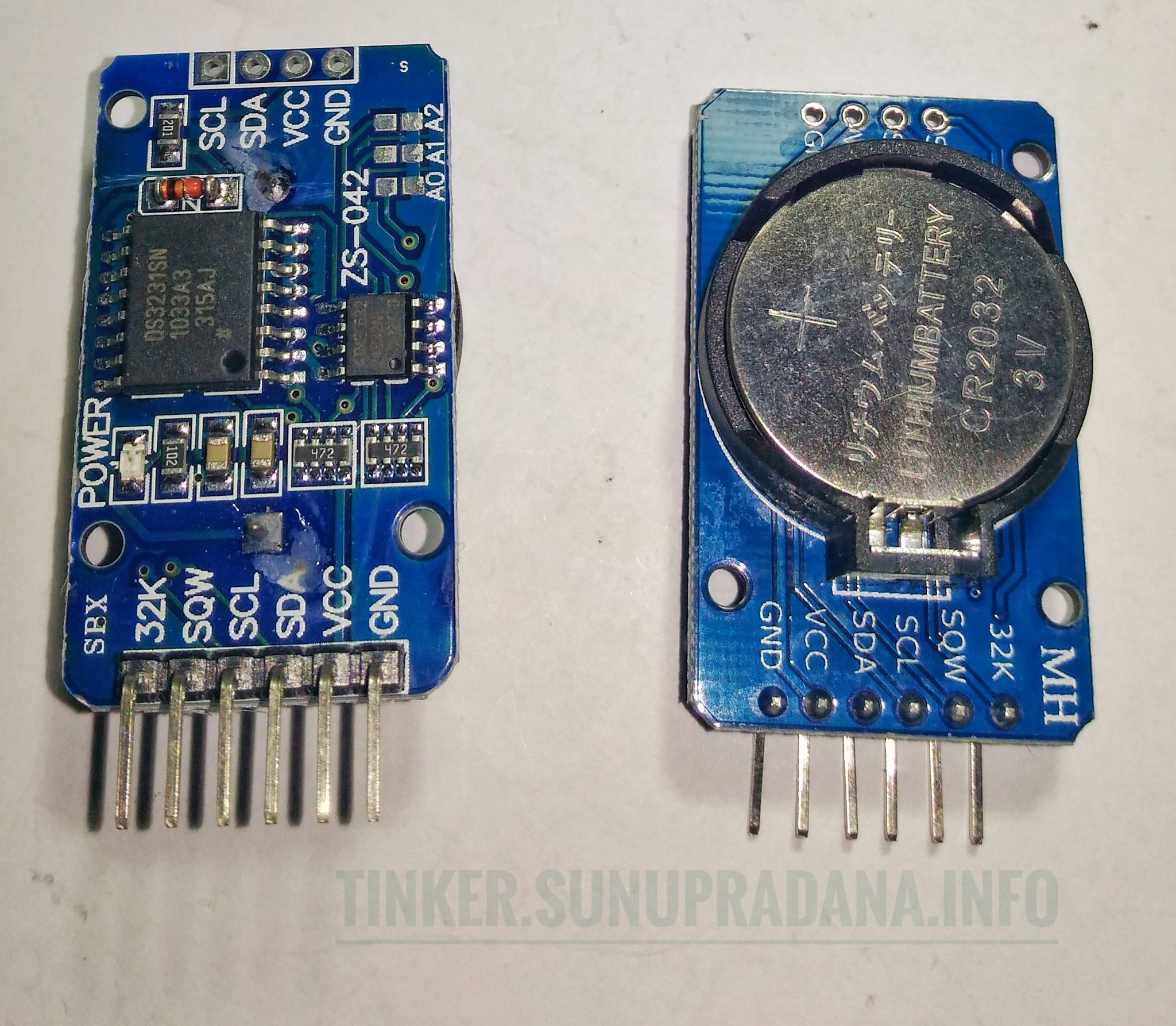
 Gambar 2. [
 Gambar 3. [sumber:
 Gambar 4. [
 Gambar 5.
 Gambar 6.
 Gambar 7.
 Gambar 8.
 Gambar 9. [
 Gambar 10.