Tujuh tahun lalu (2016) saya mencoba STM8 dan mendokumentasikannya di sini. Seiring waktu, teknologi yang dikembangkan secara sistematis untuk mempermudah pemrograman semakin matang. Saat ini STM8 sudah sedemikian mudah untuk diprogram dengan mempergunakan Arduino IDE dengan dialek bahasa turunan C dan C++.
Gambar 1.Gambar 2.Gambar 3.
Arduino IDE
Cara pertama di artikel ini adalah dengan melakukan standar pengujian kode kedip (blink). LED di papan yang akan diatur terhubung dengan D3 (PB5).
Gambar 4.
[sourcecode]
/*
* Kode kedip untuk menguji STM8 (STM8s103f3 | stm8s103?3)
*
*/
#define onBoardLED 3
void setup() {
pinMode(onBoardLED, OUTPUT);
}
void loop() {
digitalWrite(onBoardLED, HIGH); // LED OFF
delay(400);
digitalWrite(onBoardLED, LOW); // LED ON
delay(200);
}
[/sourcecode]
Gambar 5.
Eksekusi perintah “Burn Bootloader” seperti di Gambar 5 sebelum melakukan pemrograman sistem STM8 untuk pertama kali.
Gambar 6. Pemrograman telah berhasil dilakukan.
Berikutnya, dicoba pengaturan yang lebih kompleks, yaitu pemanfaatan fasilitas PWM.
[sourcecode]
/*
Dimodifikasi dari kode aslinya
Blink without Delay
created 2005
by David A. Mellis
modified 8 Feb 2010
by Paul Stoffregen
modified 11 Nov 2013
by Scott Fitzgerald
modified 9 Jan 2017
by Arturo Guadalupi
// constants won’t change. Used here to set a pin number:
const int ledPin = 3;// D3 (PB5 di papan STM8S103F3)
const int pwmTestA = 5;
const int pwmTestB = 13;
// Variables will change:
int pinState = LOW; // pinState used to set the LED
// Generally, you should use "unsigned long" for variables that hold time
// The value will quickly become too large for an int to store
unsigned long previousMillis = 0; // will store last time LED was updated
// constants won’t change:
const long interval = 10; // interval at which to blink (milliseconds)
void setup() {
// set the digital pin as output:
pinMode(ledPin, OUTPUT);
pinMode(pwmTestA, OUTPUT);
pinMode(pwmTestB, OUTPUT);
}
void loop() {
// here is where you’d put code that needs to be running all the time.
// check to see if it’s time to blink the LED; that is, if the difference
// between the current time and last time you blinked the LED is bigger than
// the interval at which you want to blink the LED.
unsigned long currentMillis = millis();
if (currentMillis - previousMillis >= interval) {
// save the last time you blinked the LED
previousMillis = currentMillis;
// if the LED is off turn it on and vice-versa:
if (pinState == LOW) {
pinState = HIGH; //LED OFF
} else {
pinState = LOW; //LED ON
}
// set the LED with the pinState of the variable:
digitalWrite(ledPin, pinState);
analogWrite(pwmTestA, 50);
analogWrite(pwmTestB, 50);
}
}
[/sourcecode]
Cara pemrograman kode terakhir ini sama seperti sebelumnya. Dengan logic analyzer bisa dilihat lebar pulsa low kode kedip (Gambar 7) dan periode (frekuensi) PWM di D5 (PC3) di Gambar 8.
Gambar 7.Gambar 8.
Berikutnya dengan bantuan oscilloscope ATTEN (f/w Siglent) bisa dilihat lebar pulsa high PWM di pin D13 (PD4).
Gambar 9.Gambar 10.
Juga dengan bantuan fasilitas di oscilloscope bisa dilihat dengan lebih baik profil rise time dari sinyal digital yang dibangkitkan oleh fasilitas PWM di STM8 (dengan pemrograman via Arduino).
SDCC STM8FLASH
Hampir sama dengan sebelumnya, berikut dicoba kembali kode program kedip dengan SDCC. Versi SDCC yang dipakai adalah 3.8.0 #10562 (Linux).
[sourcecode]
#include "stm8l.h"
int main() {
int d;
// Configure pins
PB_DDR = 0x20;
PB_CR1 = 0x20;
// Loop
do {
PB_ODR ^= 0x20;
for(d = 0; d < 29000; d++) { }
} while(1);
}
[/sourcecode]
Penetapan nilai heksadesimal 0x20 (0b00100000) untuk PB_DDR (DDR5), PB_CR1 (C15), dan PB_ODR (ODR5) dapat dipelajari dari kutipan tabel berikut ini (sumber).
Jika papan stm8 baru pertama kali diprogram, beberapa perintah berikut ini perlu dijalankan untuk menghilangkan write protection (ROP /Read Out Protection ).
Berikutnya sebagai contoh program kedip disimpan di file yang diberi nama blinky.c. Untuk melakukan kompilasi, compiler sdcc yang dipergunakan. Sedangkan untuk memasukkan kode mesin hasil kompilasi, software stm8flash yang dipakai.
[intense_code type=”block”]
sdcc -lstm8 -mstm8 -out-fmt-ihx blinky.c
stm8flash -c stlinkv2 -p stm8s103?3 -w blinky.ihx
[/intense_code]
Gambar 11. Hasil kompilasi dan flashing STM8.Gambar 12.Gambar 13.Gambar 14. [Sumber]
Module supports external voltage input of the 4-way acquisition (voltage input range of 0-5v)
integrated photoresistor
integrated thermistor
integrated potentiometer
Modules power indicator
Modules with DA output indicator, when the module DA output interface voltage reaches a certain value, will be lit panel the DA output indicator, the higher the voltage, the more obvious indicator brightness
Remove shunts to bypass on board integrated devices
The PCF8591 is a monolithically integrated, and a separate power supply, low-power, 8-bit CMOS data acquisition devices. The PCF8591 has the four analog inputs, one analog output and a serial I2C bus interface. PCF8591 three address pins A0, A1 and A2 can be used in hardware address programmed 8 PCF8591 device allows access to the same I2C bus, without the need for additional hardware. On the PCF8591 device input and output of the address, control and data signals are transmitted in serial fashion via the two-wire bidirectional I2C bus.
PCF8591 IC Features
Single power supply
PCF8591 operating voltage range of 2.5V-6V
Low standby current
Via I2C bus serial input / output
PCF8591 by 3 hardware address pins addressing
PCF8591 I2C bus speed sampling rate decided
4 analog inputs programmable single-ended or differential input
Automatic incremental channel selection
PCF8591 analog voltage range from VSS to VDD
PCF8591 built-in track-and-hold circuit
8-bit successive approximation A / D converter
1 analog output DAC gain
Module Features
Module chip using PCF8951
Module supports external voltage input of the 4-way acquisition (voltage input range of 0-5v)
The module integrated photoresistor by AD collection precise value of the ambient light intensity
Module integrated thermistor by the precise value of the ambient temperature of the AD acquisition
Module integrated 1 channel 0-5V voltage input acquisition (the blue potentiometer to adjust the input voltage)
Modules with power indicator (for the module power supply indicator lights)
Modules with DA output indicator, when the module DA output interface voltage reaches a certain value, will be lit panel the DA output indicator, the higher the voltage, the more obvious indicator brightness;
Module PCB size: 3.6cm * 2.3cm
Standard double panel, thickness 1.6mm, nice layout, surrounded by a through-hole, aperture: 3mm, convenient fixed
Module interface specification
The module on the left and right, respectively, to expand outside the 2-way pin header, respectively, as follows:
The left
AOUT chip DA output interface
AINO chip analog input interface 0
AIN1 chip analog input interface 1
AIN2 chip analog input interface 2
AIN3 chip analog input interface 3
The right
SCL – IIC clock interface connected to microcontroller IO port
SDA – IIC digital interface connected to microcontroller IO port
Papan logic level converter sering diperlukan jika bekerja dengan dua atau lebih sistem yang mempergunakan tingkat tegangan yang berbeda. Sistem yang bekerja di tingkat tegangan 3.3 V dan tidak memiliki toleransi tegangan sampai 5 V akan sangat mungkin mengalami kerusakan. Untuk mencegahnya diperlukan sistem yang mengalihkan level logika digital dari sistem 5 V dari dan ke level 3.3 V.
Penggunaan sistemnya cukup sederhana, yang penting untuk diingat adalah bahwa sumber tegangan di kedua sisi perlu dihubungkan. Jika misalnya sisi 3.3 V tidak memiliki catau daya sendiri maka pergunakan sumber lain dengan tegangan yang sama sebesar 3.3 V. Contohnya dari papan Arduino, hubungkan 5 V dan 3.3 V ke pin masing-masing yang sesuai. Adapun pin Gnd sudah terhubung antar sisi, sehingga level yang dikonversi diukur berdasarkan acuan yang sama. Jadi, Gnd untuk sistem (termasuk untuk ground sisi 3.3 V) bisa didapatkan hanya dari satu hubungan ke GND pada papan Arduino.
Do you have a 3.3V I2C or SPI sensor that might go up in smoke if connected to a 5V Arduino? Or a 5V device that needs a workaround to be compatible with your 3.3V Raspberry Pi, Arduino Due or pcDuino?
To get over this obstacle you need a device that can shift 3.3V up to 5V or 5V down to 3.3V. This is called logic level shifting. Level shifting is a dilemma so common we designed a simple PCB assembly to make interfacing devices a little easier: the Bi-Directional Logic Level Converter.
As digital devices get smaller and faster, once ubiquitous 5 V logic has given way to ever lower-voltage standards like 3.3 V, 2.5 V, and even 1.8 V, leading to an ecosystem of components that need a little help talking to each other. For example, a 5 V part might fail to read a 3.3 V signal as high, and a 3.3 V part might be damaged by a 5 V signal. This level shifter solves these problems by offering bidirectional voltage translation of up to four independent signals, converting between logic levels as low as 1.5 V on the lower-voltage side and as high as 18 V on the higher-voltage side, and its compact size and breadboard-compatible pin spacing make it easy to integrate into projects.
Gambar 4.
This logic level converter requires two supply voltages: the lower-voltage logic supply (1.5 V to 7 V) connects to the LV pin and the higher-voltage supply (LV to 18 V) connects to the HV pin. The HV supply must be higher than the LV supply for proper operation. Logic low voltages will pass directly from Hx to the corresponding Lx (and vice versa), while logic high voltages will be converted between the HV level to the LV level as the signal passes from Hx to Lx or Lx to Hx.
Sebagai awalan pengujian sebaiknya dilakukan hanya dengan tegangan DC yang relatif stabil (rata) di input terlebih dahulu. Ukur level tegangan input dan level tegangan output. Apakah nilai tegangan 5 V sudah benar turun (dikonversi) menjadi 3.3 V? Apakah, sebaliknya juga, level tegangan bisa naik dari 3.3 V ke 5 V? Berikutnya baru lakukan percobaan dengan penyakelaran gelombang kotak, karena bentuk gelombang ini adalah bentuk gelombang digital yang paling umum dipergunakaan. Mulailah dari frekuensi rendah dengan pulsa high yang cukup lebar, lalu persempit lebar pulsa high. Teruskan dengan menaikkan frekuensi dan ulangi prosedur mempersempit pulsa high seperti langkah sebelumnya. Demikian seterusnya sampai anda lihat batas lebar pulsa dan/atau batas frekuensi di mana logic converter tidak lagi berfungsi dengan baik.
Gambar 6.
Di Gambar 6, saya mencoba mengggunakan pembangkit gelombang kotak PWM yang sudah sangat banyak dijual bebas di pasaran. Frekuensi yang dipakai diatur sebesar 200 Hz (terukur 201 Hz) dan seperti terlihat di Gambar 6, duty cycle diatur sebesar 20%. Tegangan keluaran modul ini sekitar sebesar 5 V peak.
Gambar 7.
Di Gambar 7 terlihat percobaan pengukuran di sisi tegangan logic level yang lebih rendah. Frekuensi penyakelaran tetap 200 Hz, tetapi lebar pulsa hanya sebesar 40 μS. Tegangan Vpp yang terukur masih sekitar 3.97 V, level tegangan yang jelas masih lebih tinggi dari 3.3 V.
Gambar 8.
Gambar 8 adalah contoh percobaan konversi dari level tegangan sistem digital 3.3 V ke sistem digital 5 V. Sistem sumber yang dipakai adalah yang menggunakan keluarga ARM STM32. Frekuensi diatur mendekati 500 Hz (496 Hz) dengan lebar pulsa high sebesar 14 μS. Hasil konversi akan terlihat seperti di Gambar 9, level tegangan output adalah Vmax 5.31 V atau Vpp 5.63 V menurut alat ukur yang dipakai.
Keterangan mengenai RTC (Real-Time Clock) sudah pernah disampaikan melalui kutipan di post terdahulu. Di halaman itu yang dibahas adalah komponen RTC DS1307, yang lazim diperdagangkan dalam bentuk papan yang ditandai sebagai Tiny RTC. Kali ini saya coba rangkumkan mengenai DS3231 dari berbagai sumber sebagai awalan untuk memperlajarinya. RTC ini dilaporkan memiliki akurasi yang lebih baik dari RTC DS1307.
Gambar 1.
With a backup button cell (e.g. CR2032) on the underside of the module, these DS1307 modules will keep time even when disconnected from the main power source for months and even years on end. However, in our experimental projects (using this RTC with an Arduino for dataloggers amongst other things), we have found these DS1307 modules to vary hugely in their time-keeping accuracy – some gaining/losing a few seconds per day, and others gaining/losing as much as 3-5 minutes per day. While they have proved to be very consistent – i.e. a unit which gains 3 minutes per day will gain 3 minutes per day every day – having to test each unit individually over a few days and then modifying the Arduino project code to cancel out errors is not practical.
Some of the error is caused by ambient temperature changes affecting the accuracy of the timing of the crystal resonator. Some more of the error is also caused by the quality of the crystal itself and its attachment to the PCB in these economical modules.
In extensive testing we have found the time-keeping of these modules to be excellent. The DS3231 chip on the module is marketed as being accurate to 2ppm (parts per million), which means less than one second lost or gained every 5 to 6 days. The units we have tested thus far have all come in at under 1ppm accuracy, so a couple of seconds at most lost or gained per month.
This accuracy is achieved in part by the incorporation of a temperature sensor in the DS3231 which can compensate for changes in ambient temperature. The measurements from this temperature sensor are also accessible to the user (accurate to +/- 3 Celcius) which makes for a handy extra feature. These DS3231 modules also have 32kb of available EEPROM memory which can be utilised by your projects, and many other useful features.
Place the RTClib folder in your arduinosketchfolder/libraries/ folder.
You may need to create the libraries subfolder if its your first library. Restart the IDE.
Please note that dayOfTheWeek() ranges from 0 to 6 inclusive with 0 being ‘Sunday’
Compatibility
ATmega328 @ 16MHz : Arduino UNO, Adafruit Pro Trinket 5V, Adafruit Metro 328, Adafruit Metro Mini
There are several examples that will help you get started. They range from simple to complex and are always a good reference.
Connecting the Devices
The RTC devices expose two digital wires labeled SDA and SCL. These need to be connected to the wires exposed by your Arduino board labeled the same way. This varies from board to board so you will need to consult the Arduino reference documents for which pins are the SDA and SCL.
For ESP8266, these default to SDA = GPIO04 and SCL = GPIO05.
The RTC devices also require power. Make sure that VCC is connected to the proper voltage that your device requires. DS1307 requires 5v while the DS3231 can use either 3.3v or 5v. The GND must be connected to the Arduino GND even if you are not powering the RTC from the Arduino voltage pins.
RtcDateTime object
This object will be used to get and set the date and time. It supports being constructed with various time formats from strings to standard Epoch time formats. It also supports access to individual date and time value for year, month, day, hour, minute, and seconds.
RtcTemperature object
This object will be used to get the temperature from the RTC module if it supports it.
RtcDS1307 object
This object will expose the features of the DS1307 RTC chip including access to the onboard memory.
RtcDS3231 object
This object will expose the features of the DS3231 RTC chip including access to the two alarm features.
// Date and time functions using a DS3231 RTC connected via I2C and Wire lib
#include <Wire.h>
#include "RTClib.h"
RTC_DS3231 rtc;
char daysOfTheWeek[7][12] = {"Sunday", "Monday", "Tuesday", "Wednesday", "Thursday", "Friday", "Saturday"};
void setup () {
#ifndef ESP8266
  while (!Serial); // for Leonardo/Micro/Zero
#endif
  Serial.begin(9600);
  delay(3000); // wait for console opening
  if (! rtc.begin()) {
    Serial.println("Couldn't find RTC");
    while (1);
  }
  if (rtc.lostPower()) {
    Serial.println("RTC lost power, lets set the time!");
    // following line sets the RTC to the date & time this sketch was compiled
    rtc.adjust(DateTime(F(__DATE__), F(__TIME__)));
    // This line sets the RTC with an explicit date & time, for example to set
    // January 21, 2014 at 3am you would call:
    // rtc.adjust(DateTime(2014, 1, 21, 3, 0, 0));
  }
}
void loop () {
    DateTime now = rtc.now();
    Serial.print(now.year(), DEC);
    Serial.print('/');
    Serial.print(now.month(), DEC);
    Serial.print('/');
    Serial.print(now.day(), DEC);
    Serial.print(" (");
    Serial.print(daysOfTheWeek[now.dayOfTheWeek()]);
    Serial.print(") ");
    Serial.print(now.hour(), DEC);
    Serial.print(':');
    Serial.print(now.minute(), DEC);
    Serial.print(':');
    Serial.print(now.second(), DEC);
    Serial.println();
    Serial.print(" since midnight 1/1/1970 = ");
    Serial.print(now.unixtime());
    Serial.print("s = ");
    Serial.print(now.unixtime() / 86400L);
    Serial.println("d");
    // calculate a date which is 7 days and 30 seconds into the future
    DateTime future (now + TimeSpan(7,12,30,6));
    Serial.print(" now + 7d + 30s: ");
    Serial.print(future.year(), DEC);
    Serial.print('/');
    Serial.print(future.month(), DEC);
    Serial.print('/');
    Serial.print(future.day(), DEC);
    Serial.print(' ');
    Serial.print(future.hour(), DEC);
    Serial.print(':');
    Serial.print(future.minute(), DEC);
    Serial.print(':');
    Serial.print(future.second(), DEC);
    Serial.println();
    Serial.println();
    delay(3000);
}
// CONNECTIONS:
// DS3231 SDA --> SDA
// DS3231 SCL --> SCL
// DS3231 VCC --> 3.3v or 5v
// DS3231 GND --> GND
#if defined(ESP8266)
#include <pgmspace.h>
#else
#include <avr/pgmspace.h>
#endif
/* for software wire use below
#include <SoftwareWire.h>  // must be included here so that Arduino library object file references work
#include <RtcDS3231.h>
SoftwareWire myWire(SDA, SCL);
RtcDS3231<SoftwareWire> Rtc(myWire);
 for software wire use above */
/* for normal hardware wire use below */
#include <Wire.h> // must be included here so that Arduino library object file references work
#include <RtcDS3231.h>
RtcDS3231<TwoWire> Rtc(Wire);
/* for normal hardware wire use above */
void setup ()
{
    Serial.begin(9600);
    Serial.print("compiled: ");
    Serial.print(__DATE__);
    Serial.println(__TIME__);
    //--------RTC SETUP ------------
    Rtc.Begin();
    // if you are using ESP-01 then uncomment the line below to reset the pins to
    // the available pins for SDA, SCL
    // Wire.begin(0, 2); // due to limited pins, use pin 0 and 2 for SDA, SCL
    RtcDateTime compiled = RtcDateTime(__DATE__, __TIME__);
    printDateTime(compiled);
    Serial.println();
    if (!Rtc.IsDateTimeValid())
    {
        // Common Cuases:
        //    1) first time you ran and the device wasn't running yet
        //    2) the battery on the device is low or even missing
        Serial.println("RTC lost confidence in the DateTime!");
        // following line sets the RTC to the date & time this sketch was compiled
        // it will also reset the valid flag internally unless the Rtc device is
        // having an issue
        Rtc.SetDateTime(compiled);
    }
    if (!Rtc.GetIsRunning())
    {
        Serial.println("RTC was not actively running, starting now");
        Rtc.SetIsRunning(true);
    }
    RtcDateTime now = Rtc.GetDateTime();
    if (now < compiled)
    {
        Serial.println("RTC is older than compile time!  (Updating DateTime)");
        Rtc.SetDateTime(compiled);
    }
    else if (now > compiled)
    {
        Serial.println("RTC is newer than compile time. (this is expected)");
    }
    else if (now == compiled)
    {
        Serial.println("RTC is the same as compile time! (not expected but all is fine)");
    }
    // never assume the Rtc was last configured by you, so
    // just clear them to your needed state
    Rtc.Enable32kHzPin(false);
    Rtc.SetSquareWavePin(DS3231SquareWavePin_ModeNone);
}
void loop ()
{
    if (!Rtc.IsDateTimeValid())
    {
        // Common Cuases:
        //    1) the battery on the device is low or even missing and the power line was disconnected
        Serial.println("RTC lost confidence in the DateTime!");
    }
    RtcDateTime now = Rtc.GetDateTime();
    printDateTime(now);
    Serial.println();
    RtcTemperature temp = Rtc.GetTemperature();
    Serial.print(temp.AsFloat());
    Serial.println("C");
    delay(10000); // ten seconds
}
#define countof(a) (sizeof(a) / sizeof(a[0]))
void printDateTime(const RtcDateTime& dt)
{
    char datestring[20];
    snprintf_P(datestring,
            countof(datestring),
            PSTR("%02u/%02u/%04u %02u:%02u:%02u"),
            dt.Month(),
            dt.Day(),
            dt.Year(),
            dt.Hour(),
            dt.Minute(),
            dt.Second() );
    Serial.print(datestring);
}
Kode program Arduino untuk melakukan scanning peralatan dengan protokol i2c yang terhubung dengan papan Arduino.
 // --------------------------------------
// i2c_scanner
//
// Version 1
//    This program (or code that looks like it)
//    can be found in many places.
//    For example on the Arduino.cc forum.
//    The original author is not know.
// Version 2, Juni 2012, Using Arduino 1.0.1
//     Adapted to be as simple as possible by Arduino.cc user Krodal
// Version 3, Feb 26  2013
//    V3 by louarnold
// Version 4, March 3, 2013, Using Arduino 1.0.3
//    by Arduino.cc user Krodal.
//    Changes by louarnold removed.
//    Scanning addresses changed from 0...127 to 1...119,
//    according to the i2c scanner by Nick Gammon
//    http://www.gammon.com.au/forum/?id=10896
// Version 5, March 28, 2013
//    As version 4, but address scans now to 127.
//    A sensor seems to use address 120.
// Version 6, November 27, 2015.
//    Added waiting for the Leonardo serial communication.
//
//
// This sketch tests the standard 7-bit addresses
// Devices with higher bit address might not be seen properly.
//
#include <Wire.h>
void setup()
{
  Wire.begin();
  Serial.begin(9600);
  while (!Serial);             // Leonardo: wait for serial monitor
  Serial.println("nI2C Scanner");
}
void loop()
{
  byte error, address;
  int nDevices;
  Serial.println("Scanning...");
  nDevices = 0;
  for(address = 1; address < 127; address++ )
  {
    // The i2c_scanner uses the return value of
    // the Write.endTransmisstion to see if
    // a device did acknowledge to the address.
    Wire.beginTransmission(address);
    error = Wire.endTransmission();
    if (error == 0)
    {
      Serial.print("I2C device found at address 0x");
      if (address<16)
        Serial.print("0");
      Serial.print(address,HEX);
      Serial.println("  !");
      nDevices++;
    }
    else if (error==4)
    {
      Serial.print("Unknown error at address 0x");
      if (address<16)
        Serial.print("0");
      Serial.println(address,HEX);
    }
  }
  if (nDevices == 0)
    Serial.println("No I2C devices foundn");
  else
    Serial.println("donen");
  delay(5000);           // wait 5 seconds for next scan
}
#include "Wire.h"
//alamat ini juga cocok di sistem saya,ubah jika perlu
#define DS3231_I2C_ADDRESS 0x68
// Convert normal decimal numbers to binary coded decimal
byte decToBcd(byte val)
{
  return( (val/10*16) + (val%10) );
}
// Convert binary coded decimal to normal decimal numbers
byte bcdToDec(byte val)
{
  return( (val/16*10) + (val%16) );
}
void setup()
{
  Wire.begin();
  Serial.begin(9600);
  // set the initial time here:
  // DS3231 seconds, minutes, hours, day, date, month, year
  // setDS3231time(30,42,21,4,26,11,14);
}
void setDS3231time(byte second, byte minute, byte hour, byte dayOfWeek, byte
dayOfMonth, byte month, byte year)
{
  // sets time and date data to DS3231
  Wire.beginTransmission(DS3231_I2C_ADDRESS);
  Wire.write(0); // set next input to start at the seconds register
  Wire.write(decToBcd(second)); // set seconds
  Wire.write(decToBcd(minute)); // set minutes
  Wire.write(decToBcd(hour)); // set hours
  Wire.write(decToBcd(dayOfWeek)); // set day of week (1=Sunday, 7=Saturday)
  Wire.write(decToBcd(dayOfMonth)); // set date (1 to 31)
  Wire.write(decToBcd(month)); // set month
  Wire.write(decToBcd(year)); // set year (0 to 99)
  Wire.endTransmission();
}
void readDS3231time(byte *second,
byte *minute,
byte *hour,
byte *dayOfWeek,
byte *dayOfMonth,
byte *month,
byte *year)
{
  Wire.beginTransmission(DS3231_I2C_ADDRESS);
  Wire.write(0); // set DS3231 register pointer to 00h
  Wire.endTransmission();
  Wire.requestFrom(DS3231_I2C_ADDRESS, 7);
  // request seven bytes of data from DS3231 starting from register 00h
  *second = bcdToDec(Wire.read() & 0x7f);
  *minute = bcdToDec(Wire.read());
  *hour = bcdToDec(Wire.read() & 0x3f);
  *dayOfWeek = bcdToDec(Wire.read());
  *dayOfMonth = bcdToDec(Wire.read());
  *month = bcdToDec(Wire.read());
  *year = bcdToDec(Wire.read());
}
void displayTime()
{
  byte second, minute, hour, dayOfWeek, dayOfMonth, month, year;
  // retrieve data from DS3231
  readDS3231time(&second, &minute, &hour, &dayOfWeek, &dayOfMonth, &month,
  &year);
  // send it to the serial monitor
  Serial.print(hour, DEC);
  // convert the byte variable to a decimal number when displayed
  Serial.print(":");
  if (minute<10)
  {
    Serial.print("0");
  }
  Serial.print(minute, DEC);
  Serial.print(":");
  if (second<10)
  {
    Serial.print("0");
  }
  Serial.print(second, DEC);
  Serial.print(" ");
  Serial.print(dayOfMonth, DEC);
  Serial.print("/");
  Serial.print(month, DEC);
  Serial.print("/");
  Serial.print(year, DEC);
  Serial.print(" Day of week: ");
  //Urutan hari dalam minggu sudah diubah
  switch(dayOfWeek){
  // case 1:
  case 0:
    Serial.println("Sunday");
    break;
  case 1:
    Serial.println("Monday");
    break;
  case 2:
    Serial.println("Tuesday");
    break;
  case 3:
    Serial.println("Wednesday");
    break;
  case 4:
    Serial.println("Thursday");
    break;
  case 5:
    Serial.println("Friday");
    break;
  case 6:
    Serial.println("Saturday");
    break;
  }
}
void loop()
{
  displayTime(); // display the real-time clock data on the Serial Monitor,
  delay(1000); // every second
}
Sistem ini dirancang untuk bekerja dengan menggunakan baterai “khusus”, yaitu baterai yang bisa diisi ulang (rechargeable) seperti LIR2032. Di papan sudah disediakan sistem pengisian ulang untuk baterai tersebut. Karena itu jika kita mempergunakan baterai tipe yang tidak bisa diisi ulang (non-rechargeable) seperti CR2032 maka ada perubahan yang perlu dilakukan. Hal ini untuk mencegah agar baterai primer yang tidak bisa diisi ulang itu tidak berusaha diisi oleh sistem. Caranya adalah dengan melepas/membuang diode seperti pada Gambar 3 berikut.
A real-time clock (RTC) is a computer clock (most often in the form of an integrated circuit) that keeps track of the current time.
Although the term often refers to the devices in personal computers, servers and embedded systems, RTCs are present in almost any electronic device which needs to keep accurate time.
A real time clock is basically just like a watch - it runs on a battery and keeps time for you even when there is a power outage! Using an RTC, you can keep track of long timelines, even if you reprogram your microcontroller or disconnect it from USB or a power plug.
Most microcontrollers, including the Arduino, have a built-in timekeeper called millis() and there are also timers built into the chip that can keep track of longer time periods like minutes or days. So why would you want to have a separate RTC chip? Well, the biggest reason is that millis() only keeps track of time since the Arduino was last powered - . That means that when the power is turned on, the millisecond timer is set back to 0. The Arduino doesn’t know that it’s ‘Tuesday’ or ‘March 8th’, all it can tell is ‘It’s been 14,000 milliseconds since I was last turned on’.
OK so what if you wanted to set the time on the Arduino? You’d have to program in the date and time and you could have it count from that point on. But if it lost power, you’d have to reset the time. Much like very cheap alarm clocks: every time they lose power they blink 12:00
While this sort of basic timekeeping is OK for some projects, some projects such as data-loggers, clocks, etc will need to have consistent timekeeping that doesn’t reset when the Arduino battery dies or is reprogrammed. Thus, we include a separate RTC! The RTC chip is a specialized chip that just keeps track of time. It can count leap-years and knows how many days are in a month, but it doesn’t take care of Daylight Savings Time (because it changes from place to place).
Real time clocks (RTC), as the name recommends are clock modules. The DS1307 real time clock (RTC) IC is an 8 pin device using an I2C interface. The DS1307 is a low-power clock/calendar with 56 bytes of battery backup SRAM. The clock/calendar provides seconds, minutes, hours, day, date, month and year qualified data. The end date of each month is automatically adjusted, especially for months with less than 31 days.
They are available as integrated circuits (ICs) and supervise timing like a clock and also operate date like a calendar. The main advantage of RTC is that they have an arrangement of battery backup which keeps the clock/calendar running even if there is power failure. An exceptionally little current is required for keeping the RTC animated. We can find these RTCs in many applications like embedded systems and computer mother boards, etc.
Both modules use the I2C bus, which makes connection very easy. If you’re not sure about the I2C bus and Arduino, check out the I2C tutorials (chapters 20 and 21), or review chapter seventeen of my book “Arduino Workshop“.
Moving on – first you will need to identify which pins on your Arduino or compatible boards are used for the I2C bus – these will be knows as SDA (or data) and SCL (or clock).
Place the RTClib folder in your arduinosketchfolder/libraries/ folder.
You may need to create the libraries subfolder if its your first library. Restart the IDE.
Please note that dayOfTheWeek() ranges from 0 to 6 inclusive with 0 being ‘Sunday’
Compatibility
ATmega328 @ 16MHz : Arduino UNO, Adafruit Pro Trinket 5V, Adafruit Metro 328, Adafruit Metro Mini
There are several examples that will help you get started. They range from simple to complex and are always a good reference.
Connecting the Devices
The RTC devices expose two digital wires labeled SDA and SCL. These need to be connected to the wires exposed by your Arduino board labeled the same way. This varies from board to board so you will need to consult the Arduino reference documents for which pins are the SDA and SCL.
For ESP8266, these default to SDA = GPIO04 and SCL = GPIO05.
The RTC devices also require power. Make sure that VCC is connected to the proper voltage that your device requires. DS1307 requires 5v while the DS3231 can use either 3.3v or 5v. The GND must be connected to the Arduino GND even if you are not powering the RTC from the Arduino voltage pins.
RtcDateTime object This object will be used to get and set the date and time. It supports being constructed with various time formats from strings to standard Epoch time formats. It also supports access to individual date and time value for year, month, day, hour, minute, and seconds.
RtcTemperature object This object will be used to get the temperature from the RTC module if it supports it.
RtcDS1307 object This object will expose the features of the DS1307 RTC chip including access to the onboard memory.
RtcDS3231 object This object will expose the features of the DS3231 RTC chip including access to the two alarm features.
void setup ()
{
while (!Serial); // for Leonardo/Micro/Zero
// Serial.begin(57600);
Serial.begin(9600);
if (! rtc.begin())
{
Serial.println("Couldn’t find RTC");
while (1);
}
if (! rtc.isrunning())
{
Serial.println("RTC is NOT running!");
// following line sets the RTC to the date & time this sketch was compiled
// rtc.adjust(DateTime(F(__DATE__), F(__TIME__)));
// This line sets the RTC with an explicit date & time, for example to set
// January 21, 2014 at 3am you would call:
// rtc.adjust(DateTime(2014, 1, 21, 3, 0, 0));
}
}
#if defined(ARDUINO_ARCH_SAMD)
// for Zero, output on USB Serial console, remove line below if using programming port to program the Zero!
#define Serial SerialUSB
#endif
[code lang=”C”]// SQW/OUT pin mode using a DS1307 RTC connected via I2C.
//
// According to the data sheet (http://datasheets.maxim-ic.com/en/ds/DS1307.pdf), the
// DS1307’s SQW/OUT pin can be set to low, high, 1Hz, 4.096kHz, 8.192kHz, or 32.768kHz.
//
// This sketch reads the state of the pin, then iterates through the possible values at
// 5 second intervals.
//
// NOTE:
// You must connect a pull up resistor (~10kohm) from the SQW pin up to VCC. Without
// this pull up the wave output will not work!
#include <Wire.h>
#include "RTClib.h"
#if defined(ARDUINO_ARCH_SAMD)
// for Zero, output on USB Serial console, remove line below if using programming port to program the Zero!
#define Serial SerialUSB
#endif
RTC_DS1307 rtc;
int mode_index = 0;
Ds1307SqwPinMode modes[] = {OFF, ON, SquareWave1HZ, SquareWave4kHz, SquareWave8kHz, SquareWave32kHz};
Serial.print("Sqw Pin Mode: ");
switch(mode) {
case OFF: Serial.println("OFF"); break;
case ON: Serial.println("ON"); break;
case SquareWave1HZ: Serial.println("1Hz"); break;
case SquareWave4kHz: Serial.println("4.096kHz"); break;
case SquareWave8kHz: Serial.println("8.192kHz"); break;
case SquareWave32kHz: Serial.println("32.768kHz"); break;
default: Serial.println("UNKNOWN"); break;
}
}
void setup () {
#ifndef ESP8266
while (!Serial); // for Leonardo/Micro/Zero
#endif
// Serial.begin(57600);
Serial.begin(9600);
if (! rtc.begin()) {
Serial.println("Couldn’t find RTC");
while (1);
}
[code lang=”C”]// Example of using the non-volatile RAM storage on the DS1307.
// You can write up to 56 bytes from address 0 to 55.
// Data will be persisted as long as the DS1307 has battery power.
#include <Wire.h>
#include "RTClib.h"
#if defined(ARDUINO_ARCH_SAMD)
// for Zero, output on USB Serial console, remove line below if using programming port to program the Zero!
#define Serial SerialUSB
#endif
#ifndef ESP8266
while (!Serial); // for Leonardo/Micro/Zero
#endif
// Serial.begin(57600);
Serial.begin(9600);
rtc.begin();
// Print old RAM contents on startup.
Serial.println("Current NVRAM values:");
for (int i = 0; i < 6; ++i) {
printnvram(i);
}
// Write some bytes to non-volatile RAM storage.
// NOTE: You can only read and write from addresses 0 to 55 (i.e. 56 byte values).
Serial.println("Writing NVRAM values.");
// Example writing one byte at a time:
rtc.writenvram(0, 0xFE);
rtc.writenvram(1, 0xED);
// Example writing multiple bytes:
uint8_t writeData[4] = { 0xBE, 0xEF, 0x01, 0x02 };
rtc.writenvram(2, writeData, 4);
// Read bytes from non-volatile RAM storage.
Serial.println("Reading NVRAM values:");
// Example reading one byte at a time.
Serial.println(rtc.readnvram(0), HEX);
Serial.println(rtc.readnvram(1), HEX);
// Example reading multiple bytes:
uint8_t readData[4] = {0};
rtc.readnvram(readData, 4, 2);
Serial.println(readData[0], HEX);
Serial.println(readData[1], HEX);
Serial.println(readData[2], HEX);
Serial.println(readData[3], HEX);
}
void loop () {
// Do nothing in the loop.
}
[/code]
[code lang=”C”]// Date and time functions using just software, based on millis() & timer
#include <Arduino.h>
#include <Wire.h> // this #include still required because the RTClib depends on it
#include "RTClib.h"
#if defined(ARDUINO_ARCH_SAMD)
// for Zero, output on USB Serial console, remove line below if using programming port to program the Zero!
#define Serial SerialUSB
#endif
// following line sets the RTC to the date & time this sketch was compiled
rtc.begin(DateTime(F(__DATE__), F(__TIME__)));
// This line sets the RTC with an explicit date & time, for example to set
// January 21, 2014 at 3am you would call:
// rtc.adjust(DateTime(2014, 1, 21, 3, 0, 0));
}
/* for software wire use below
#include <SoftwareWire.h> // must be included here so that Arduino library object file references work
#include <RtcDS1307.h>
SoftwareWire myWire(SDA, SCL);
RtcDS1307<SoftwareWire> Rtc(myWire);
for software wire use above */
/* for normal hardware wire use below */
#include <Wire.h> // must be included here so that Arduino library object file references work
#include <RtcDS1307.h>
RtcDS1307<TwoWire> Rtc(Wire);
/* for normal hardware wire use above */
//——-RTC SETUP ————
// if you are using ESP-01 then uncomment the line below to reset the pins to
// the available pins for SDA, SCL
// Wire.begin(0, 2); // due to limited pins, use pin 0 and 2 for SDA, SCL
if (!Rtc.IsDateTimeValid())
{
// Common Cuases:
// 1) first time you ran and the device wasn’t running yet
// 2) the battery on the device is low or even missing
Serial.println("RTC lost confidence in the DateTime!");
// following line sets the RTC to the date & time this sketch was compiled
// it will also reset the valid flag internally unless the Rtc device is
// having an issue
Rtc.SetDateTime(compiled);
}
if (!Rtc.GetIsRunning())
{
Serial.println("RTC was not actively running, starting now");
Rtc.SetIsRunning(true);
}
RtcDateTime now = Rtc.GetDateTime();
if (now < compiled)
{
Serial.println("RTC is older than compile time! (Updating DateTime)");
Rtc.SetDateTime(compiled);
}
else if (now > compiled)
{
Serial.println("RTC is newer than compile time. (this is expected)");
}
else if (now == compiled)
{
Serial.println("RTC is the same as compile time! (not expected but all is fine)");
}
// never assume the Rtc was last configured by you, so
// just clear them to your needed state
Rtc.SetSquareWavePin(DS1307SquareWaveOut_Low);
}
void loop ()
{
if (!Rtc.IsDateTimeValid())
{
// Common Cuases:
// 1) the battery on the device is low or even missing and the power line was disconnected
Serial.println("RTC lost confidence in the DateTime!");
}
/* for software wire use below
#include <SoftwareWire.h> // must be included here so that Arduino library object file references work
#include <RtcDS1307.h>
SoftwareWire myWire(SDA, SCL);
RtcDS1307<SoftwareWire> Rtc(myWire);
for software wire use above */
/* for normal hardware wire use below */
#include <Wire.h> // must be included here so that Arduino library object file references work
#include <RtcDS1307.h>
RtcDS1307<TwoWire> Rtc(Wire);
/* for normal hardware wire use above */
//——-RTC SETUP ————
// if you are using ESP-01 then uncomment the line below to reset the pins to
// the available pins for SDA, SCL
// Wire.begin(0, 2); // due to limited pins, use pin 0 and 2 for SDA, SCL
if (!Rtc.IsDateTimeValid())
{
Serial.println(“RTC lost confidence in the DateTime!”);
Rtc.SetDateTime(compiled);
}
if (!Rtc.GetIsRunning())
{
Serial.println(“RTC was not actively running, starting now”);
Rtc.SetIsRunning(true);
}
RtcDateTime now = Rtc.GetDateTime();
if (now < compiled)
{
Serial.println(“RTC is older than compile time! (Updating DateTime)”);
Rtc.SetDateTime(compiled);
}
// never assume the Rtc was last configured by you, so
// just clear them to your needed state
Rtc.SetSquareWavePin(DS1307SquareWaveOut_Low);
/* comment out on a second run to see that the info is stored long term */
// Store something in memory on the RTC
Rtc.SetMemory(0, 13);
uint8_t written = Rtc.SetMemory(13, (const uint8_t*)data, sizeof(data) - 1); // remove the null terminator strings add
Rtc.SetMemory(1, written);
/* end of comment out section */
}
void loop ()
{
if (!Rtc.IsDateTimeValid())
{
// Common Cuases:
// 1) the battery on the device is low or even missing and the power line was disconnected
Serial.println(“RTC lost confidence in the DateTime!”);
}
RtcDateTime now = Rtc.GetDateTime();
printDateTime(now);
Serial.println();
delay(5000);
// read data
// get the offset we stored our data from address zero
uint8_t address = Rtc.GetMemory(0);
if (address != 13)
{
Serial.println(“address didn’t match”);
}
else
{
// get the size of the data from address 1
uint8_t count = Rtc.GetMemory(1);
uint8_t buff[20];
// get our data from the address with the given size
uint8_t gotten = Rtc.GetMemory(address, buff, count);
void setup ()
{
Serial.begin(9600);
Wire.begin();
RTC.begin();
if (! RTC.isrunning())
{
Serial.println("RTC is NOT running!");
// following line sets the RTC to the date & time this sketch was compiled
RTC.adjust(DateTime(__DATE__, __TIME__));
}
}
void loop ()
{
DateTime now = RTC.now();
Serial.print(now.year(), DEC);
Serial.print(‘/’);
Serial.print(now.month(), DEC);
Serial.print(‘/’);
Serial.print(now.day(), DEC);
Serial.print(‘ ‘);
Serial.print(now.hour(), DEC);
Serial.print(‘:’);
Serial.print(now.minute(), DEC);
Serial.print(‘:’);
Serial.print(now.second(), DEC);
Serial.println();
Serial.println("Uji RTC");
Serial.println(" ");
byte decToBcd(byte val){
// Convert normal decimal numbers to binary coded decimal
return ( (val/10*16) + (val%10) );
}
byte bcdToDec(byte val) {
// Convert binary coded decimal to normal decimal numbers
return ( (val/16*10) + (val%16) );
}
void printDate(){
// Reset the register pointer
Wire.beginTransmission(DS1307_ADDRESS);
Wire.write(zero);
Wire.endTransmission();
Wire.requestFrom(DS1307_ADDRESS, 7);
int second = bcdToDec(Wire.read());
int minute = bcdToDec(Wire.read());
int hour = bcdToDec(Wire.read() & 0b111111); //24 hour time
int weekDay = bcdToDec(Wire.read()); //0-6 -> sunday - Saturday
int monthDay = bcdToDec(Wire.read());
int month = bcdToDec(Wire.read());
int year = bcdToDec(Wire.read());
//print the date EG 3/1/11 23:59:59
Serial.print(month);
Serial.print("/");
Serial.print(monthDay);
Serial.print("/");
Serial.print(year);
Serial.print(" ");
Serial.print(hour);
Serial.print(":");
Serial.print(minute);
Serial.print(":");
Serial.println(second);
Infrared IR Receiver Module Wireless Remote Control Kit For Arduino
Description:
Arduino mini infrared wireless remote control kit consists of ultra-thin infrared remote control and 38KHz infrared receiver module. This mini slim infrared remote control with 20 function keys. Its transmit distances up to 8 meters. Ideal for handling a variety of equipment indoors.
IR receiver module can receive standard 38KHz modulation remote control signal. You can decode the remote control signal through Arduino programming. You can design a variety of remote control robots and interactive works.
Specification:
Transmission distance: up to 8m(depending on the surrounding environment, sensitivity of receiver etc)
Battery: CR2025 button battery
Battery capacity: 160mAh
Effective angle: 60°
Sticking material: 0.125mmPET
Effective life: 20,000 times
Static current: 3uA – 5uA
Dynamic current: 3mA – 5mA
The IR Remote supplied with this Set looks like this (Others may also be supplied):
- Based on NEC protocol; Built-in 1 x AG10 battery;
- Remote control range: above 8m;
- Wavelength: 940Nm;
- Frequency: crystal oscillator: 455KHz; IR carrier frequency: 38KHz
This is especially good for remote control of a small robot, using the arrow buttons. Below is [ps2id url=’#terryyourduino’ offset=’300′]an example Software Sketch[/ps2id] for this remote. The reported buttons will be Forward, Left, Right, Reverse (for the 4 blue button), OK for the red ‘OK’ button, 1 to 0 for the white number buttons, and ‘*’ and ‘#’ for the bottom red buttons.
TYPES OF IR REMOTE CONTROLS
NOTE!! Most handheld remotes are shipped with a small clear plastic piece in the battery compartment that must be removed to activate it. You can usually just pull it out.
There are many different IR remote controls. Some from YourDuino.com are the low-cost IR Infrared Remote Control Kit 2 and also the THIS IR Remote (right) which has directional buttons that would be good for controlling a vehicle etc. Then, there are the typical TV and Stereo Remotes. All of these may have different encoding methods and number of physical buttons, and different codes received when a button is pressed. Below we will give [ps2id url=’#terryyourduino’ offset=’300′]example Software Sketches[/ps2id] for a few common IR Remotes.
NOTE!! If you have a late version of Arduino with a library IRRobotRemote, it may conflict and you may have to remove that library. Make sure to delete Arduino_Root/libraries/RobotIRremote. Where Arduino_Root refers to the install directory of Arduino. The library RobotIRremote has similar definitions to IRremote and causes errors.
Contoh salah satu tabel output dari IR remote control (cocok untuk IR RC Keyes warna hitam dengan tombol arah).
Untuk contoh kode lihat di [ps2id url=’#xindacode’ offset=’350′] bagian halaman ini.[/ps2id]
[/su_panel]
[su_panel border=”3px solid #30C0F0″ radius=”10″]
The IRremote library treats the different protocols as follows:
NEC: 32 bits are transmitted, most-significant bit first. (protocol details)
Sony: 12 or more bits are transmitted, most-significant bit first. Typically 12 or 20 bits are used. Note that the official protocol is least-significant bit first. (protocol details) For more details, I’ve written an article that describes the Sony protocol in much more detail: Understanding Sony IR remote codes.
RC5: 12 or more bits are transmitted most-significant bit first. The message starts with the two start bits, which are not part of the code values. (protocol details)
RC6: 20 (typically) bits are transmitted, most-significant bit first. The message starts with a leader pulse, and a start bit, which is not part of the code values. The fourth bit is transmitted double-wide, since it is the trailer bit. (protocol details)
For Sony and RC5/6, each transmission must be repeated 3 times as specified in the protocol. The transmission code does not implement the RC5/6 toggle bit; that is up to the caller.
The IRrecv library consists of two parts. An interrupt routine is called every 50 microseconds, measures the length of the marks and spaces, and saves the durations in a buffer. The user calls a decoding routine to decode the buffered measurements into the code value that was sent (typically 11 to 32 bits).
The decode library tries decoding different protocols in succession, stopping if one succeeds. It returns a structure that contains the raw data, the decoded data, the number of bits in the decoded data, and the protocol used to decode the data.
For decoding, the MATCH macro determine if the measured mark or space time is approximately equal to the expected time.
The RC5/6 decoding is a bit different from the others because RC5/6 encode bits with mark + space or space + mark, rather than by durations of marks and spaces. The getRClevel helper method splits up the durations and gets the mark/space level of a single time interval.
For repeated transmissions (button held down), the decoding code will return the same decoded value over and over. The exception is NEC, which sends a special repeat code instead of repeating the transmission of the value. In this case, the decode routine returns a special REPEAT value.
In more detail, the receiver’s interrupt code is called every time the TIMER1 overflows, which is set to happen after 50 microseconds. At each interrupt, the input status is checked and the timer counter is incremented. The interrupt routine times the durations of marks (receiving a modulated signal) and spaces (no signal received), and records the durations in a buffer. The first duration is the length of the gap before the transmission starts. This is followed by alternating mark and space measurements. All measurements are in “ticks” of 50 microseconds.
The interrupt routine is implemented as a state machine. It starts in STATE_IDLE, which waits for the gap to end. When a mark is received, it moves to STATE_MARK which times the duration of the mark. It then alternates between STATE_MARK and STATE_SPACE to time marks and spaces. When a space of sufficiently long duration is received, the state moves to STATE_STOP, indicating a full transmission is received. The interrupt routine continues to time the gap, but blocks in this state.
The STATE_STOP is used a a flag to indicate to the decode routine that a full transmission is available. When processing is done, the resume() method sets the state to STATE_IDLE so the interrupt routine can start recording the next transmission. There are a few things to note here. Gap timing continues during STATE_STOP and STATE_IDLE so an accurate measurement of the time between transmissions can be obtained. If resume() is not called before the next transmission starts, the partial transmission will be discarded. The motivation behind the stop/resume is to ensure the receive buffer is not overwritten while it is still being processed; debugging becomes very difficult if the buffer is constantly changing.
Details of the sending library
The transmission code is straightforward. To ensure accurate output frequencies and duty cycles, I use the PWM timer, rather than delay loops to modulate the output LED at the appropriate frequency. (See my Arduino PWM Secrets article for more details on the PWM timers.) At the low level, enableIROut sets up the timer for PWM output on pin 3 at the proper frequency. The mark() method sends a mark by enabling PWM output and delaying the specified time. The space() method sends a space by disabling PWM output and delaying the specified time.
If you’re running the test receiving sketch and getting a seemingly random stream of hex digits, try turning off the lights in the room. Some fluorescent lights can confuse 38KHz IR receivers just enough to corrupt the data.
ESP8266 is supported in a fork based on an old codebase that isn’t as recent, but it works reasonably well given that perfectly timed sub millisecond interrupts are different on that chip. See https://github.com/markszabo/IRremoteESP8266
The following sketch will receive codes and print them to the serial port. This sketch is very useful for testing IR receiving, and for determining what code values to use in your code. A slightly more complex version is in the examples directory as IRrecvDump.
This sketch also illustrates how to perform an action while a button is pressed. In this example, the action is writing to the serial port.
//------------------------------------------------------------------------------
// Include the IRremote library header
//
#include <IRremote.h>
//------------------------------------------------------------------------------
// Tell IRremote which Arduino pin is connected to the IR Receiver (TSOP4838)
//
int recvPin = 7;
IRrecv irrecv(recvPin);
//+=============================================================================
// Configure the Arduino
//
void  setup ( )
{
  Serial.begin(9600);   // Status message will be sent to PC at 9600 baud
  irrecv.enableIRIn();  // Start the receiver
}
//+=============================================================================
// Display IR code
//
void  ircode (decode_results *results)
{
  // Panasonic has an Address
  if (results->decode_type == PANASONIC) {
    Serial.print(results->address, HEX);
    Serial.print(":");
  }
  // Print Code
  Serial.print(results->value, HEX);
}
//+=============================================================================
// Display encoding type
//
void  encoding (decode_results *results)
{
  switch (results->decode_type) {
    default:
    case UNKNOWN:      Serial.print("UNKNOWN");       break ;
    case NEC:          Serial.print("NEC");           break ;
    case SONY:         Serial.print("SONY");          break ;
    case RC5:          Serial.print("RC5");           break ;
    case RC6:          Serial.print("RC6");           break ;
    case DISH:         Serial.print("DISH");          break ;
    case SHARP:        Serial.print("SHARP");         break ;
    case JVC:          Serial.print("JVC");           break ;
    case SANYO:        Serial.print("SANYO");         break ;
    case MITSUBISHI:   Serial.print("MITSUBISHI");    break ;
    case SAMSUNG:      Serial.print("SAMSUNG");       break ;
    case LG:           Serial.print("LG");            break ;
    case WHYNTER:      Serial.print("WHYNTER");       break ;
    case AIWA_RC_T501: Serial.print("AIWA_RC_T501");  break ;
    case PANASONIC:    Serial.print("PANASONIC");     break ;
    case DENON:        Serial.print("Denon");         break ;
  }
}
//+=============================================================================
// Dump out the decode_results structure.
//
void  dumpInfo (decode_results *results)
{
  // Check if the buffer overflowed
  if (results->overflow) {
    Serial.println("IR code too long. Edit IRremoteInt.h and increase RAWBUF");
    return;
  }
  // Show Encoding standard
  Serial.print("Encoding  : ");
  encoding(results);
  Serial.println("");
  // Show Code & length
  Serial.print("Code      : ");
  ircode(results);
  Serial.print(" (");
  Serial.print(results->bits, DEC);
  Serial.println(" bits)");
}
//+=============================================================================
// Dump out the decode_results structure.
//
void  dumpRaw (decode_results *results)
{
  // Print Raw data
  Serial.print("Timing[");
  Serial.print(results->rawlen-1, DEC);
  Serial.println("]: ");
  for (int i = 1;  i < results->rawlen;  i++) {
    unsigned long  x = results->rawbuf[i] * USECPERTICK;
    if (!(i & 1)) {  // even
      Serial.print("-");
      if (x < 1000)  Serial.print(" ") ;
      if (x < 100)   Serial.print(" ") ;
      Serial.print(x, DEC);
    } else {  // odd
      Serial.print("     ");
      Serial.print("+");
      if (x < 1000)  Serial.print(" ") ;
      if (x < 100)   Serial.print(" ") ;
      Serial.print(x, DEC);
      if (i < results->rawlen-1) Serial.print(", "); //',' not needed for last one
    }
    if (!(i % 8))  Serial.println("");
  }
  Serial.println("");                    // Newline
}
//+=============================================================================
// Dump out the decode_results structure.
//
void  dumpCode (decode_results *results)
{
  // Start declaration
  Serial.print("unsigned int  ");          // variable type
  Serial.print("rawData[");                // array name
  Serial.print(results->rawlen - 1, DEC);  // array size
  Serial.print("] = {");                   // Start declaration
  // Dump data
  for (int i = 1;  i < results->rawlen;  i++) {
    Serial.print(results->rawbuf[i] * USECPERTICK, DEC);
    if ( i < results->rawlen-1 ) Serial.print(","); // ',' not needed on last one
    if (!(i & 1))  Serial.print(" ");
  }
  // End declaration
  Serial.print("};");  //
  // Comment
  Serial.print("  // ");
  encoding(results);
  Serial.print(" ");
  ircode(results);
  // Newline
  Serial.println("");
  // Now dump "known" codes
  if (results->decode_type != UNKNOWN) {
    // Some protocols have an address
    if (results->decode_type == PANASONIC) {
      Serial.print("unsigned int  addr = 0x");
      Serial.print(results->address, HEX);
      Serial.println(";");
    }
    // All protocols have data
    Serial.print("unsigned int  data = 0x");
    Serial.print(results->value, HEX);
    Serial.println(";");
  }
}
//+=============================================================================
// The repeating section of the code
//
void  loop ( )
{
  decode_results  results;        // Somewhere to store the results
  if (irrecv.decode(&results)) {  // Grab an IR code
    dumpInfo(&results);           // Output the results
    dumpRaw(&results);            // Output the results in RAW format
    dumpCode(&results);           // Output the results as source code
    Serial.println("");           // Blank line between entries
    irrecv.resume();              // Prepare for the next value
  }
}
/*
 * IRremote: IRrecvDemo - demonstrates receiving IR codes with IRrecv
 * An IR detector/demodulator must be connected to the input RECV_PIN.
 * Version 0.1 July, 2009
 * Copyright 2009 Ken Shirriff
 * http://arcfn.com
 */
#include <IRremote.h>
int RECV_PIN = 7;
int RELAY_PIN = 4;
IRrecv irrecv(RECV_PIN);
decode_results results;
// Dumps out the decode_results structure.
// Call this after IRrecv::decode()
// void * to work around compiler issue
//void dump(void *v) {
//  decode_results *results = (decode_results *)v
void dump(decode_results *results) {
  int count = results->rawlen;
  if (results->decode_type == UNKNOWN) {
    Serial.println("Could not decode message");
  }
  else {
    if (results->decode_type == NEC) {
      Serial.print("Decoded NEC: ");
    }
    else if (results->decode_type == SONY) {
      Serial.print("Decoded SONY: ");
    }
    else if (results->decode_type == RC5) {
      Serial.print("Decoded RC5: ");
    }
    else if (results->decode_type == RC6) {
      Serial.print("Decoded RC6: ");
    }
    Serial.print(results->value, HEX);
    Serial.print(" (");
    Serial.print(results->bits, DEC);
    Serial.println(" bits)");
  }
  Serial.print("Raw (");
  Serial.print(count, DEC);
  Serial.print("): ");
  for (int i = 0; i < count; i++) {
    if ((i % 2) == 1) {
      Serial.print(results->rawbuf[i]*USECPERTICK, DEC);
    }
    else {
      Serial.print(-(int)results->rawbuf[i]*USECPERTICK, DEC);
    }
    Serial.print(" ");
  }
  Serial.println("");
}
void setup()
{
  pinMode(RELAY_PIN, OUTPUT);
  pinMode(13, OUTPUT);
    Serial.begin(9600);
  irrecv.enableIRIn(); // Start the receiver
}
int on = 0;
unsigned long last = millis();
void loop() {
  if (irrecv.decode(&results)) {
    // If it's been at least 1/4 second since the last
    // IR received, toggle the relay
    if (millis() - last > 250) {
      on = !on;
      digitalWrite(RELAY_PIN, on ? HIGH : LOW);
      digitalWrite(13, on ? HIGH : LOW);
      dump(&results);
    }
    last = millis();
    irrecv.resume(); // Receive the next value
  }
}
/*
 * IRremote: IRremoteInfo - prints relevant config info & settings for IRremote over serial
 * Intended to help identify & troubleshoot the various settings of IRremote
 * For example, sometimes users are unsure of which pin is used for Tx or the RAWBUF values
 * This example can be used to assist the user directly or with support.
 * Intended to help identify & troubleshoot the various settings of IRremote
 * Hopefully this utility will be a useful tool for support & troubleshooting for IRremote
 * Check out the blog post describing the sketch via http://www.analysir.com/blog/2015/11/28/helper-utility-for-troubleshooting-irremote/
 * Version 1.0 November 2015
 * Original Author: AnalysIR - IR software & modules for Makers & Pros, visit http://www.AnalysIR.com
 */
#include <IRremote.h>
void setup()
{
  // Serial.begin(115200); //You may alter the BAUD rate here as needed
  Serial.begin(9600); //You may alter the BAUD rate here as needed
  while (!Serial); //wait until Serial is established - required on some Platforms
  //Runs only once per restart of the Arduino.
  dumpHeader();
  dumpRAWBUF();
  dumpTIMER();
  dumpTimerPin();
  dumpClock();
  dumpPlatform();
  dumpPulseParams();
  dumpSignalParams();
  dumpArduinoIDE();
  dumpDebugMode();
  dumpProtocols();
  dumpFooter();
}
void loop() {
  //nothing to do!
}
void dumpRAWBUF() {
  Serial.print(F("RAWBUF: "));
  Serial.println(RAWBUF);
}
void dumpTIMER() {
  boolean flag = false;
#ifdef IR_USE_TIMER1
  Serial.print(F("Timer defined for use: ")); Serial.println(F("Timer1")); flag = true;
#endif
#ifdef IR_USE_TIMER2
  Serial.print(F("Timer defined for use: ")); Serial.println(F("Timer2")); flag = true;
#endif
#ifdef IR_USE_TIMER3
  Serial.print(F("Timer defined for use: ")); Serial.println(F("Timer3")); flag = true;
#endif
#ifdef IR_USE_TIMER4
  Serial.print(F("Timer defined for use: ")); Serial.println(F("Timer4")); flag = true;
#endif
#ifdef IR_USE_TIMER5
  Serial.print(F("Timer defined for use: ")); Serial.println(F("Timer5")); flag = true;
#endif
#ifdef IR_USE_TIMER4_HS
  Serial.print(F("Timer defined for use: ")); Serial.println(F("Timer4_HS")); flag = true;
#endif
#ifdef IR_USE_TIMER_CMT
  Serial.print(F("Timer defined for use: ")); Serial.println(F("Timer_CMT")); flag = true;
#endif
#ifdef IR_USE_TIMER_TPM1
  Serial.print(F("Timer defined for use: ")); Serial.println(F("Timer_TPM1")); flag = true;
#endif
#ifdef IR_USE_TIMER_TINY0
  Serial.print(F("Timer defined for use: ")); Serial.println(F("Timer_TINY0")); flag = true;
#endif
  if (!flag) {
    Serial.print(F("Timer Error: ")); Serial.println(F("not defined"));
  }
}
void dumpTimerPin() {
  Serial.print(F("IR Tx Pin: "));
  Serial.println(TIMER_PWM_PIN);
}
void dumpClock() {
  Serial.print(F("MCU Clock: "));
  Serial.println(F_CPU);
}
void dumpPlatform() {
  Serial.print(F("MCU Platform: "));
#if defined(__AVR_ATmega1280__)
  Serial.println(F("Arduino Mega1280"));
#elif  defined(__AVR_ATmega2560__)
  Serial.println(F("Arduino Mega2560"));
#elif defined(__AVR_AT90USB162__)
  Serial.println(F("Teensy 1.0 / AT90USB162"));
  // Teensy 2.0
#elif defined(__AVR_ATmega32U4__)
  Serial.println(F("Arduino Leonardo / Yun / Teensy 1.0 / ATmega32U4"));
#elif defined(__MK20DX128__) || defined(__MK20DX256__)
  Serial.println(F("Teensy 3.0 / Teensy 3.1 / MK20DX128 / MK20DX256"));
#elif defined(__MKL26Z64__)
  Serial.println(F("Teensy-LC / MKL26Z64"));
#elif defined(__AVR_AT90USB646__)
  Serial.println(F("Teensy++ 1.0 / AT90USB646"));
#elif defined(__AVR_AT90USB1286__)
  Serial.println(F("Teensy++ 2.0 / AT90USB1286"));
#elif defined(__AVR_ATmega1284__) || defined(__AVR_ATmega1284P__)
  Serial.println(F("ATmega1284"));
#elif defined(__AVR_ATmega644__) || defined(__AVR_ATmega644P__)
  Serial.println(F("ATmega644"));
#elif defined(__AVR_ATmega324P__) || defined(__AVR_ATmega324A__) || defined(__AVR_ATmega324PA__)
  Serial.println(F("ATmega324"));
#elif defined(__AVR_ATmega164A__) || defined(__AVR_ATmega164P__)
  Serial.println(F("ATmega164"));
#elif defined(__AVR_ATmega128__)
  Serial.println(F("ATmega128"));
#elif defined(__AVR_ATmega88__) || defined(__AVR_ATmega88P__)
  Serial.println(F("ATmega88"));
#elif defined(__AVR_ATmega64__)
  Serial.println(F("ATmega64"));
#elif defined(__AVR_ATmega48__) || defined(__AVR_ATmega48P__)
  Serial.println(F("ATmega48"));
#elif defined(__AVR_ATmega32__)
  Serial.println(F("ATmega32"));
#elif defined(__AVR_ATmega16__)
  Serial.println(F("ATmega16"));
#elif defined(__AVR_ATmega8535__)
  Serial.println(F("ATmega8535"));
#elif defined(__AVR_ATmega8__)
  Serial.println(F("Atmega8"));
#elif defined(__AVR_ATtiny84__)
  Serial.println(F("ATtiny84"));
#elif defined(__AVR_ATtiny85__)
  Serial.println(F("ATtiny85"));
#else
  Serial.println(F("ATmega328(P) / (Duemilanove, Diecimila, LilyPad, Mini, Micro, Fio, Nano, etc)"));
#endif
}
void dumpPulseParams() {
  Serial.print(F("Mark Excess: ")); Serial.print(MARK_EXCESS);; Serial.println(F(" uSecs"));
  Serial.print(F("Microseconds per tick: ")); Serial.print(USECPERTICK);; Serial.println(F(" uSecs"));
  Serial.print(F("Measurement tolerance: ")); Serial.print(TOLERANCE); Serial.println(F("%"));
}
void dumpSignalParams() {
  Serial.print(F("Minimum Gap between IR Signals: ")); Serial.print(_GAP); Serial.println(F(" uSecs"));
}
void dumpDebugMode() {
  Serial.print(F("Debug Mode: "));
#if DEBUG
  Serial.println(F("ON"));
#else
  Serial.println(F("OFF (Normal)"));
#endif
}
void dumpArduinoIDE() {
  Serial.print(F("Arduino IDE version: "));
  Serial.print(ARDUINO / 10000);
  Serial.write('.');
  Serial.print((ARDUINO % 10000) / 100);
  Serial.write('.');
  Serial.println(ARDUINO % 100);
}
void dumpProtocols() {
  Serial.println(); Serial.print(F("IR PROTOCOLS  "));  Serial.print(F("SEND     "));  Serial.println(F("DECODE"));
  Serial.print(F("============= "));  Serial.print(F("======== "));  Serial.println(F("========"));
  Serial.print(F("RC5:          "));  printSendEnabled(SEND_RC5);  printDecodeEnabled(DECODE_RC6);
  Serial.print(F("RC6:          "));  printSendEnabled(SEND_RC6);  printDecodeEnabled(DECODE_RC5);
  Serial.print(F("NEC:          "));  printSendEnabled(SEND_NEC);  printDecodeEnabled(DECODE_NEC);
  Serial.print(F("SONY:         "));  printSendEnabled(SEND_SONY);  printDecodeEnabled(DECODE_SONY);
  Serial.print(F("PANASONIC:    "));  printSendEnabled(SEND_PANASONIC);  printDecodeEnabled(DECODE_PANASONIC);
  Serial.print(F("JVC:          "));  printSendEnabled(SEND_JVC);  printDecodeEnabled(DECODE_JVC);
  Serial.print(F("SAMSUNG:      "));  printSendEnabled(SEND_SAMSUNG);  printDecodeEnabled(DECODE_SAMSUNG);
  Serial.print(F("WHYNTER:      "));  printSendEnabled(SEND_WHYNTER);  printDecodeEnabled(DECODE_WHYNTER);
  Serial.print(F("AIWA_RC_T501: "));  printSendEnabled(SEND_AIWA_RC_T501);  printDecodeEnabled(DECODE_AIWA_RC_T501);
  Serial.print(F("LG:           "));  printSendEnabled(SEND_LG);  printDecodeEnabled(DECODE_LG);
  Serial.print(F("SANYO:        "));  printSendEnabled(SEND_SANYO);  printDecodeEnabled(DECODE_SANYO);
  Serial.print(F("MITSUBISHI:   "));  printSendEnabled(SEND_MITSUBISHI);  printDecodeEnabled(DECODE_MITSUBISHI);
  Serial.print(F("DISH:         "));  printSendEnabled(SEND_DISH);  printDecodeEnabled(DECODE_DISH);
  Serial.print(F("SHARP:        "));  printSendEnabled(SEND_SHARP);  printDecodeEnabled(DECODE_SHARP);
  Serial.print(F("DENON:        "));  printSendEnabled(SEND_DENON);  printDecodeEnabled(DECODE_DENON);
  Serial.print(F("PRONTO:       "));  printSendEnabled(SEND_PRONTO);  Serial.println(F("(Not Applicable)"));
}
void printSendEnabled(int flag) {
  if (flag) {
    Serial.print(F("Enabled  "));
  }
  else {
    Serial.print(F("Disabled "));
  }
}
void printDecodeEnabled(int flag) {
  if (flag) {
    Serial.println(F("Enabled"));
  }
  else {
    Serial.println(F("Disabled"));
  }
}
void dumpHeader() {
  Serial.println(F("IRremoteInfo - by AnalysIR (http://www.AnalysIR.com/)"));
  Serial.println(F("             - A helper sketch to assist in troubleshooting issues with the library by reviewing the settings within the IRremote library"));
  Serial.println(F("             - Prints out the important settings within the library, which can be configured to suit the many supported platforms"));
  Serial.println(F("             - When seeking on-line support, please post or upload the output of this sketch, where appropriate"));
  Serial.println();
  Serial.println(F("IRremote Library Settings"));
  Serial.println(F("========================="));
}
void dumpFooter() {
  Serial.println();
  Serial.println(F("Notes: "));
  Serial.println(F("     - Most of the seetings above can be configured in the following files included as part of the library"));
  Serial.println(F("     - IRremteInt.h"));
  Serial.println(F("     - IRremote.h"));
  Serial.println(F("     - You can save SRAM by disabling the Decode or Send features for any protocol (Near the top of IRremoteInt.h)"));
  Serial.println(F("     - Some Timer conflicts, with other libraries, can be easily resolved by configuring a differnt Timer for your platform"));
}
/*
 * IRremote: IRrecvDemo - demonstrates receiving IR codes with IRrecv
 * An IR detector/demodulator must be connected to the input RECV_PIN.
 * Version 0.1 July, 2009
 * Copyright 2009 Ken Shirriff
 * http://arcfn.com
 */
#include <IRremote.h>
int RECV_PIN = 7;
IRrecv irrecv(RECV_PIN);
decode_results results;
void setup()
{
  Serial.begin(9600);
  // In case the interrupt driver crashes on setup, give a clue
  // to the user what's going on.
  Serial.println("Enabling IRin");
  irrecv.enableIRIn(); // Start the receiver
  Serial.println("Enabled IRin");
}
void loop()
{
  if (irrecv.decode(&results))
  {
    Serial.println(results.value, HEX);
    irrecv.resume(); // Receive the next value
  }
  delay(100);
}
/*
 * IRremote: IRrecvDump - dump details of IR codes with IRrecv
 * An IR detector/demodulator must be connected to the input RECV_PIN.
 * Version 0.1 July, 2009
 * Copyright 2009 Ken Shirriff
 * http://arcfn.com
 * JVC and Panasonic protocol added by Kristian Lauszus (Thanks to zenwheel and other people at the original blog post)
 * LG added by Darryl Smith (based on the JVC protocol)
 */
#include <IRremote.h>
/*
*  Default is Arduino pin D11.
*  You can change this to another available Arduino Pin.
*  Your IR receiver should be connected to the pin defined here
*/
int RECV_PIN = 7;
IRrecv irrecv(RECV_PIN);
decode_results results;
void setup()
{
  Serial.begin(9600);
  irrecv.enableIRIn(); // Start the receiver
}
void dump(decode_results *results) {
  // Dumps out the decode_results structure.
  // Call this after IRrecv::decode()
  int count = results->rawlen;
  if (results->decode_type == UNKNOWN) {
    Serial.print("Unknown encoding: ");
  }
  else if (results->decode_type == NEC) {
    Serial.print("Decoded NEC: ");
  }
  else if (results->decode_type == SONY) {
    Serial.print("Decoded SONY: ");
  }
  else if (results->decode_type == RC5) {
    Serial.print("Decoded RC5: ");
  }
  else if (results->decode_type == RC6) {
    Serial.print("Decoded RC6: ");
  }
  else if (results->decode_type == PANASONIC) {
    Serial.print("Decoded PANASONIC - Address: ");
    Serial.print(results->address, HEX);
    Serial.print(" Value: ");
  }
  else if (results->decode_type == LG) {
    Serial.print("Decoded LG: ");
  }
  else if (results->decode_type == JVC) {
    Serial.print("Decoded JVC: ");
  }
  else if (results->decode_type == AIWA_RC_T501) {
    Serial.print("Decoded AIWA RC T501: ");
  }
  else if (results->decode_type == WHYNTER) {
    Serial.print("Decoded Whynter: ");
  }
  Serial.print(results->value, HEX);
  Serial.print(" (");
  Serial.print(results->bits, DEC);
  Serial.println(" bits)");
  Serial.print("Raw (");
  Serial.print(count, DEC);
  Serial.print("): ");
  for (int i = 1; i < count; i++) {
    if (i & 1) {
      Serial.print(results->rawbuf[i]*USECPERTICK, DEC);
    }
    else {
      Serial.write('-');
      Serial.print((unsigned long) results->rawbuf[i]*USECPERTICK, DEC);
    }
    Serial.print(" ");
  }
  Serial.println();
}
void loop() {
  if (irrecv.decode(&results)) {
    Serial.println(results.value, HEX);
    dump(&results);
    irrecv.resume(); // Receive the next value
  }
}
/* YourDuino.com Example Software Sketch
 Brick Starter Set IR Remote Kit Test
http://yourduino.com/sunshop2/index.php?l=product_detail&p;=364
 based on code by Ken Shirriff - http://arcfn.com
 Get Library at: https://github.com/shirriff/Arduino-IRremote
 Unzip folder into Libraries. RENAME folder IRremote
 [email protected] */
/*-----( Import needed libraries )-----*/
#include "IRremote.h"
/*-----( Declare Constants )-----*/
int receiver = 7; // pin 1 of IR receiver to Arduino digital pin 7
/*-----( Declare objects )-----*/
IRrecv irrecv(receiver);           // create instance of 'irrecv'
decode_results results;            // create instance of 'decode_results'
/*-----( Declare Variables )-----*/
void setup()   /*----( SETUP: RUNS ONCE )----*/
{
  Serial.begin(9600);
  Serial.println("YourDuino IR Receiver Button Decode Test");
  Serial.println("Questions: [email protected]");
  irrecv.enableIRIn(); // Start the receiver
}/*--(end setup )---*/
void loop()   /*----( LOOP: RUNS CONSTANTLY )----*/
{
  if (irrecv.decode(&results)) // have we received an IR signal?
  {
//    Serial.println(results.value, HEX);  UN Comment to see raw values
    translateIR();
    irrecv.resume(); // receive the next value
  }
}/* --(end main loop )-- */
/*-----( Declare User-written Functions )-----*/
void translateIR() // takes action based on IR code received
// describing KEYES Remote IR codes
{
  switch(results.value)
  {
  case 0xFF629D: Serial.println(" FORWARD"); break;
  case 0xFF22DD: Serial.println(" LEFT");    break;
  case 0xFF02FD: Serial.println(" -OK-");    break;
  case 0xFFC23D: Serial.println(" RIGHT");   break;
  case 0xFFA857: Serial.println(" REVERSE"); break;
  case 0xFF6897: Serial.println(" 1");    break;
  case 0xFF9867: Serial.println(" 2");    break;
  case 0xFFB04F: Serial.println(" 3");    break;
  case 0xFF30CF: Serial.println(" 4");    break;
  case 0xFF18E7: Serial.println(" 5");    break;
  case 0xFF7A85: Serial.println(" 6");    break;
  case 0xFF10EF: Serial.println(" 7");    break;
  case 0xFF38C7: Serial.println(" 8");    break;
  case 0xFF5AA5: Serial.println(" 9");    break;
  case 0xFF42BD: Serial.println(" *");    break;
  case 0xFF4AB5: Serial.println(" 0");    break;
  case 0xFF52AD: Serial.println(" #");    break;
  case 0xFFFFFFFF: Serial.println(" REPEAT");break;
  default:
    Serial.println(" other button   ");
  }// End Case
  delay(500); // Do not get immediate repeat
} //END translateIR
/* ( THE END ) */
#include "IRremote.h"
#include < LiquidCrystal.h>
LiquidCrystal lcd(8, 9, 4, 5, 6, 7);
int receiver = 3; // Signal Pin of IR receiver to Arduino Digital Pin 11
/*-----( Declare objects )-----*/
IRrecv irrecv(receiver);           // create instance of 'irrecv'
decode_results results;            // create instance of 'decode_results'
void setup()   /*----( SETUP: RUNS ONCE )----*/
{
  lcd.begin(16, 2);
  Serial.begin(9600);
  Serial.println("IR Receiver Button Decode");
  irrecv.enableIRIn(); // Start the receiver
  lcd.setCursor(0,0);
  lcd.print("Press any Key....");
}/*--(end setup )---*/
void loop()   /*----( LOOP: RUNS CONSTANTLY )----*/
{
  if (irrecv.decode(&results)) // have we received an IR signal?
  {
    translateIR();
    irrecv.resume(); // receive the next value
  }
}/* --(end main loop )-- */
/*-----( Function )-----*/
void translateIR() // takes action based on IR code received
{
// describing Remote IR codes
  lcd.clear();
  lcd.setCursor(0,0);
  lcd.print("Press any Key....");
  lcd.setCursor(0,1);
  switch(results.value)
  {
  case 0xFF629D: lcd.print("Key- FORWARD"); break;
  case 0xFF22DD: lcd.print("Key- LEFT");    break;
  case 0xFF02FD: lcd.print("Key- -OK-");    break;
  case 0xFFC23D: lcd.print("Key- RIGHT");   break;
  case 0xFFA857: lcd.print("Key- REVERSE"); break;
  case 0xFF6897: lcd.print("Key- 1");Serial.print("i");    break;
  case 0xFF9867: lcd.print("Key- 2");    break;
  case 0xFFB04F: lcd.print("Key- 3");    break;
  case 0xFF30CF: lcd.print("Key- 4");    break;
  case 0xFF18E7: lcd.print("Key- 5");    break;
  case 0xFF7A85: lcd.print("Key- 6");    break;
  case 0xFF10EF: lcd.print("Key- 7");    break;
  case 0xFF38C7: lcd.print("Key- 8");    break;
  case 0xFF5AA5: lcd.print("Key- 9");    break;
  case 0xFF42BD: lcd.print("Key- *");    break;
  case 0xFF4AB5: lcd.print("Key- 0");    break;
  case 0xFF52AD: lcd.print("Key- #");    break;
  case 0xFFFFFFFF: lcd.print("Key- REPEAT");break;
  default:
    Serial.println("UnKnown Signal");
  }// End Case
  delay(500); // Do not get immediate repeat
}
A rotary encoder, also called a shaft encoder, is an electro-mechanical device that converts the angular position or motion of a shaft or axle to an analog or digital signal.
There are two main types: absolute and incremental (relative). The output of absolute encoders indicates the current position of the shaft, making them angle transducers. The output of incremental encoders provides information about the motion of the shaft, which is typically further processed elsewhere into information such as speed, distance and position.
Rotary encoders are used in many applications that require precise shaft unlimited rotation—including industrial controls, robotics, special purpose photographic lenses, computer input devices (such as optomechanical mice and trackballs), controlled stress rheometers, and rotating radar platforms.
A rotary encoder is a type of position sensor which is used for determining the angular position of a rotating shaft. It generates an electrical signal, either analog or digital, according to the rotational movement.
Gambar 1.
Gambar 2.
This rotary encoder is also known as quadrature encoder or relative rotary encoder and its output is a series of square wave pulses.
An incremental rotary encoder generates two output signals while its shaft is rotating which is also called quadrature ouptut. Depending on the direction, one of the signals leads the other. You can see the output signal waveforms of an incremental rotary encoder and the expected bit sequence below.
Gambar 3.
As you can see from the figure, both of the outputs stays HIGH at the initial state. When the encoder shaft starts to rotate in clockwise direction, Output A falls to LOW first and Output B follows it with a lag. In a counter-clockwise direction the operation turns opposite. Time intervals on the waveform depend on the rotation speed but the signal lagging is guaranteed in encoder operation. We will build the whole scenario on this characteristic of the incremental rotary encoder.
The incremental encoder, sometimes called a relative encoder, is simpler in design than the absolute encoder. It consists of two tracks and two sensors whose outputs are called channels A and B. As the shaft rotates, pulse trains occur on these channels at a frequency proportional to the shaft speed, and the phase relationship between the signals yields the direction of rotation. The code disk pattern and output signals A and B are illustrated in Figure 5. By counting the number of pulses and knowing the resolution of the disk, the angular motion can be measured. The A and B channels are used to determine the direction of rotation by assessing which channels “leads” the other. The signals from the two channels are a 1/4 cycle out of phase with each other and are known as quadrature signals. Often a third output channel, called INDEX, yields one pulse per revolution, which is useful in counting full revolutions. It is also useful as a reference to define a home base or zero position.
[ps2id url=’#gambar6′ offset=’300′]Figure 5[/ps2id] illustrates two separate tracks for the A and B channels, but a more common configuration uses a single track with the A and B sensors offset a 1/4 cycle on the track to yield the same signal pattern. A single-track code disk is simpler and cheaper to manufacture.
The quadrature signals A and B can be decoded to yield the direction of rotation as hown in [ps2id url=’#gambar7′ offset=’300′]Figure 6[/ps2id]. Decoding transitions of A and B by using sequential logic circuits in different ways can provide three different resolutions of the output pulses: 1X, 2X, 4X. 1X resolution only provides a single pulse for each cycle in one of the signals A or B, 4X resolution provides a pulse at every edge transition in the two signals A and B providing four times the 1X resolution. The direction of rotation(clockwise or counter-clockwise) is determined by the level of one signal during an edge transition of the second signal. For example, in the 1X mode, A=
with B =1 implies a clockwise pulse, and B=
with A=1 implies a counter-clockwise pulse. If we only had a single output channel A or B, it would be impossible to determine the direction of rotation. Furthermore, shaft jitter around an edge transition in the single signal would result in erroneous pulses.
[code lang=”C”]
int pinA = 6; // Connected to CLK on KY-040. Gantidari pin 2
int pinB = 7; // Connected to DT on KY-040. Ganti dari pin 3
int encoderPosCount = 0;
int pinALast;
int aVal;
boolean bCW;
void setup() {
pinMode (pinA,INPUT);
pinMode (pinB,INPUT);
/* Read Pin A
Whatever state it’s in will reflect the last position
*/
pinALast = digitalRead(pinA);
Serial.begin (9600);
}
void loop() {
aVal = digitalRead(pinA);
if (aVal != pinALast){ // Means the knob is rotating
// if the knob is rotating, we need to determine direction
// We do that by reading pin B.
if (digitalRead(pinB) != aVal) { // Means pin A Changed first - We’re Rotating Clockwise
encoderPosCount ++;
bCW = true;
} else {// Otherwise B changed first and we’re moving CCW
bCW = false;
encoderPosCount-;
}
Serial.print (“Rotated: “);
if (bCW){
Serial.println (“clockwise”);
}else{
Serial.println(“counterclockwise”);
}
Serial.print(“Encoder Position: “);
Serial.println(encoderPosCount);
Serial.begin (9600);
// Reads the initial state of the outputA
aLastState = digitalRead(outputA);
}
void loop() {
aState = digitalRead(outputA); // Reads the “current” state of the outputA
// If the previous and the current state of the outputA are different, that means a Pulse has occured
if (aState != aLastState){
// If the outputB state is different to the outputA state, that means the encoder is rotating clockwise
if (digitalRead(outputB) != aState) {
counter ++;
} else {
counter -;
}
Serial.print(“Position: “);
Serial.println(counter);
}
aLastState = aState; // Updates the previous state of the outputA with the current state
}
[/code]
Description of the code: So first we need to define the pins to which our encoder is connected and define some variables needed for the program. In the setup section we need to define the two pins as inputs, start the serial communication for printing the results on the serial monitor, as well as read the initial value of the output A and put the value into the variable aLastState.
Then in the loop section we read the output A again but now we put the value into the aState variable. So if we rotate the encoder and a pulse is generated, these two values will differ and the first “if” statement will become true. Right after that using the second “if” statement we determine the rotation direction. If the output B state differ from the output A state the counter will be increased by one, else it will be decreased. At the end, after printing the results on the serial monitor, we need to update the aLastState variable with aState variable.
That’s all we need for this example. If upload the code, start the Serial Monitor and start rotating the encoder we will start getting the values in the serial monitor. The particular module that I have makes 30 counts each full cycle.
I’m a bit surprised that people try to read these switches “when they stop bouncing”. I’ve seen very elaborate hardware and software solutions for this. As far as I’m concerned, the only time I know they’re not bouncing is when they are in the “click” state, i.e. with no signal going to pins 1&2!
The Arduino can accept external interrupts on some of its pins. The goal is again to catch the rising or falling edge on pin1.
This sketch works well because the interrupt routine is very short. I works even better if a bit of hardware debouncing is forced on the rotary encoder. With two 0.1 uF capacitors soldered to the encoder pins, the number of calls to the interrupt routine is dramatically reduced. This is important because too many calls to the interrupt routine will rob computing cycles from the main routine, negating the effects of using interrupts to save computing power. It has been recommended to never connect a bouncy switch directly to a controllers interrupt pins.
Method 3: Using a Timer Interrupt
…
So, the Timer Interrupt method is the best one. Studying the code of the new Arduino Bounce library (and testing with micros() ) confirmed that the library doesn’t rely on delay() for debouncing, effectively adding very little overhead to method 1 or 3.
This solution will be perfect for my initial version of the Rotary Encoder Arduino sub-project.
If you have read this so far, please keep in mind that your results may vary. I AM ASSUMING that pin2 is stable when I accept the debounced status on pin1. Otherwise, the switch is totally unreliable.
Also, if your application needs 100% confidence that the encoder will never miss a state change, or produce false positive, just buy a better encoder. I definitely would not trust my little encoder to drive a robot or a high precision machine. Take a look at this page and you will realise that my little encoder, at $1, really is at the bottom end of the quality scale. It was definitely made for manual operation, as a volume control or, like I’m doing here, to increase and decrease a counter.
All my (Arduino) code observes the state of the rotary encoder switches once per “loop”. This has the considerable benefit of simplicity (as advocated by the KISS principle, by our belovéd Franciscan, etc). It also has the considerable risk of inadequacy!
If the encoder is to be read accurately, it must be sampled sufficiently frequently. One danger of my “simple” approach is that the “one observation per pass through the loop( )” will not constitute a sufficiently high sample rate to satisfy Shannon’s sampling theorem, such that neither direction nor speed of the encoder can be deduced. Errors will result.
Both the “correct” solutions (fast, interrupt-driven sampling of the encoder or explicit connection of the encoder to inputs with edge transition detection capability which can trigger interrupts) feel way-too complicated to me and offend against my sense of “appropriate engineering”. But the simple approach was always known to be standing on thin ice - that ice has just melted, forcing me into action.
In response to Richard’s input, I’ve finally done something, which has fixed my own rig (above) and which seems to offer a useful “taming” of the Rotary Encoder - I’ve added two capacitors!
Gambar 15.
Action of the additional capacitors is understood if you remember that there are resistors (shown dotted in the schematic above) - either fitted explicitly as extra components or embodied as internal pull-ups in the microcontroller. The combination of these resistors and the additional capacitors are going to define a time-constant (making appropriate choice of the capacitor value dependent upon the resistor) which modifies the switching action as sensed by the microcontroller…
The sketch below shows one switch closure with- (bottom) and without- (top) a capacitor fitted.
Gambar 16.
The downward transition isn’t changed. But when the switch opens, the capacitor has to be charged to build up the voltage, introducing a time delay Δt before the voltage read on the microcontroller input pin reaches the logic high value. This “stretches” the pulse width. If the pulse is stretched wider, it can be observed successfully at a lower sample rate.
The capacitors also modify switch bounce (although I think this is irrelevant, given my lamentably slow sample rate) and suppress high-frequency noise which might be induced on the otherwise high impedance line.
I can’t confirm the exact mechanism that is taming my Rotary Encoders - all I can report is that the addition of the 100nF capacitors, as shown, is doing an excellent job. I recommend that you add them to all the m0xpd rigs, VFOs, etc that use Rotary Encoders read by Arduino software.
A mechanical rotary encoder consist of switches that are opened and closed in a predetermined sequence. During the switch transitions noise is generated, typically lasting from 1 to 5 milliseconds; the switch is “bouncing”. The following photo shows a rotary encoder switching and captures the first millisecond after the swtich event. Notice that for approximate .7 milliseconds the switch is “bouncing”
Gambar 17.
In order to reliable determine the state or level of the switch, it has to be “de-bounced” either by adding hardware components to attenuate the noise or by waiting in the code sufficient time after the transition has occurred.
Hardware Debounce
The implementation here uses hardware debouncing for the rotary encoder. In consists of a capacitor across the signal pins (A, B) and GND. The pull up resistor of the Arduino input pins is enabled, and A, B are connected to these input pins.
Bourns, has a recommended implementation published in this technical paper: Signal Conditioning. It consist of an external pullup resistor and the output pins are filtered with an RC filter as shown in the following diagram:
Gambar 18.
My Choice
I decided to use hardware debounce because it is good to eliminate the noise at the source. In addition, the s/w debounce code will add a debounce (~5msec) time every time it is invoked whether the volume knob is adjusted or not. Seems like an unnecessary delay.
The no-debounce-required code is indeed very elegant: it is compact, fast and adds no delays in the code and requires no hardware debounce circuitry. However, just like in the case of the s/w debounce code, it will be executing all the time whether the rotary encoder has been turned or not. However, tt may not matter at all that the code is executing or adding delays all the time, after all the Arduino code runs in an infinite loop. The question is whether the extra execution will cause any critical delays to execution of other code.
I have just implemented the configuration as recommended by the BOURNS technical brief described above and it works very well. Because in this configuration the pull up resistors are implemented outside of arduino, the internal pull ups in Arduino are to be disabled. That is:
H/W debouncing is still recommended. If you don’t want to implement the more sophisticated approach from the Bourns paper, you can just add a couple of capacitors from the signal pins (A, B) to the common pin. Here is a photo of simple H/W debouncing from my earlier project (Experimentally, when I installed the blue capacitors (0.1uF) they did not work quite well. Had to install additional .01uF caps (marked 103) in parallel.
Even dirtier. But I supposedly had capacitors to keep this from happening. Well, I did BUT rather than connect the directly to pins 2 and 4 of the nano, I had them at the other end of the bread board just because it had been easier to put them there. I connected the caps directly between pins 2 and 4 and the ground. The noise is now gone.
With the noise problems solved, I began playing with the original code to see if I could make it ‘tighter’. I’ve used interrupts some, but I’m far from an expert and I found this website to be quite informative.
Encoder - High performance with 4X counting and very efficient interrupt routines. Uses the External Interrupt pins of the MCU. Download
ClickEncoder - For encoders with button. Works on any IO-Pin (uses a Timer), supports acceleration (rotate faster -> increment faster, feels very natural); Button reports Click, DoubleClick, Held, Released. Example Included.
SoftTimer - Has a built in driver for rotary encoders.
“Quadrature Encoders in Arduino, done right. Done right.”
- Uses “interrupt on any change of A or B” to squeeze the maximum possible resolution out of an encoder — count on both low-to-high and high-to-low transitions, both A and B.
Berikut contoh-contoh kode program, silakan membaca situs sumber aslinya untuk lebih memahami. Beberpa kode memerlukan pustaka/library yang dapat dicari melalui halaman sumber kode.
[code lang=”C”]
/*
* Dimodifikasi dari kode contoh:
* Encoder Library - Basic Example
* http://www.pjrc.com/teensy/td_libs_Encoder.html
*
* This example code is in the public domain.
*/
#include <Encoder.h>
// Change these two numbers to the pins connected to your encoder.
// Best Performance: both pins have interrupt capability.
// Pin 2 & pin 3 di Arduino Uno
// Good Performance: only the first pin has interrupt capability
// Low Performance: neither pin has interrupt capability
Encoder myEnc(6, 7);
// avoid using pins with LEDs attached
[code lang=”C”]
/* Encoder Library - NoInterrupts Example
* http://www.pjrc.com/teensy/td_libs_Encoder.html
*
* This example code is in the public domain.
*/
// If you define ENCODER_DO_NOT_USE_INTERRUPTS *before* including
// Encoder, the library will never use interrupts. This is mainly
// useful to reduce the size of the library when you are using it
// with pins that do not support interrupts. Without interrupts,
// your program must call the read() function rapidly, or risk
// missing changes in position.
#define ENCODER_DO_NOT_USE_INTERRUPTS
#include <Encoder.h>
// Beware of Serial.print() speed. Without interrupts, if you
// transmit too much data with Serial.print() it can slow your
// reading from Encoder. Arduino 1.0 has improved transmit code.
// Using the fastest baud rate also helps. Teensy has USB packet
// buffering. But all boards can experience problems if you print
// too much and fill up buffers.
// Change these two numbers to the pins connected to your encoder.
// With ENCODER_DO_NOT_USE_INTERRUPTS, no interrupts are ever
// used, even if the pin has interrupt capability
Encoder myEnc(6, 7);
// avoid using pins with LEDs attached
void loop() {
long newPos = myEnc.read();
if (newPos != position) {
position = newPos;
Serial.println(position);
}
// With any substantial delay added, Encoder can only track
// very slow motion. You may uncomment this line to see
// how badly a delay affects your encoder.
//delay(50);
}[/code]
[code lang=”C”]
// —-
// InterruptRotator.ino - Example for the RotaryEncoder library.
// This class is implemented for use with the Arduino environment.
// Copyright (c) by Matthias Hertel, http://www.mathertel.de
// This work is licensed under a BSD style license. See http://www.mathertel.de/License.aspx
// More information on: http://www.mathertel.de/Arduino
// —-
// 18.01.2014 created by Matthias Hertel
// —-
// This example checks the state of the rotary encoder in the loop() function.
// The current position is printed on output when changed.
// Hardware setup:
// Attach a rotary encoder with output pins to A2 and A3.
// The common contact should be attached to ground.
#include <RotaryEncoder.h>
// Setup a RoraryEncoder for pins A2 and A3:
RotaryEncoder encoder(A2, A3);
Serial.println(“SimplePollRotator example for the RotaryEncoder library.”);
// You may have to modify the next 2 lines if using other pins than A2 and A3
PCICR |= (1 << PCIE1); // This enables Pin Change Interrupt 1 that covers the Analog input pins or Port C.
PCMSK1 |= (1 << PCINT10) | (1 << PCINT11); // This enables the interrupt for pin 2 and 3 of Port C.
} // setup()
// The Interrupt Service Routine for Pin Change Interrupt 1
// This routine will only be called on any signal change on A2 and A3: exactly where we need to check.
ISR(PCINT1_vect)
{
encoder.tick(); // just call tick() to check the state.
}
// Read the current position of the encoder and print out when changed.
void loop()
{
static int pos = 0;
int newPos = encoder.getPosition();
if (pos != newPos)
{
Serial.print(newPos);
Serial.println();
pos = newPos;
// Just to show, that long lasting procedures don’t break the rotary encoder:
// When newPos is 66 the ouput will freeze, but the turned positions will be recognized even when not polled.
// The interrupt still works.
// The output is correct 6.6 seconds later.
if (newPos == 66)
{
// delay(6600);
delay(3000); //diubah
} // if newPOS
} // if
} // loop ()
[code lang=”C”]
// —-
// LimitedRotator.ino - Example for the RotaryEncoder library.
// This class is implemented for use with the Arduino environment.
// Copyright (c) by Matthias Hertel, http://www.mathertel.de
// This work is licensed under a BSD style license. See http://www.mathertel.de/License.aspx
// More information on: http://www.mathertel.de/Arduino
// —-
// 26.03.2017 created by Matthias Hertel
// —-
// This example checks the state of the rotary encoder in the loop() function.
// The current position is printed on output when changed.
// In addition to the SimplePollRotator example here the range of the rotator is limited to the range 0 - 16 and only incremental steps of 2 are realized.
// To implement this limit the boundaries are checked and eventually the current position is adjusted.
// The internal (physical) position of the rotary encoder library remains by stepping with the increment 1
// so the the logical position is calculated by applying the ROTARYSTEPS factor.
// Hardware setup:
// Attach a rotary encoder with output pins to A2 and A3.
// The common contact should be attached to ground.
Serial.println(“LimitedRotator example for the RotaryEncoder library.”);
encoder.setPosition(10 / ROTARYSTEPS); // start with the value of 10.
} // setup()
// Read the current position of the encoder and print out when changed.
void loop()
{
encoder.tick();
// get the current physical position and calc the logical position
int newPos = encoder.getPosition() * ROTARYSTEPS;
[code lang=”C”]
// —-
// SimplePollRotator.ino - Example for the RotaryEncoder library.
// This class is implemented for use with the Arduino environment.
// Copyright (c) by Matthias Hertel, http://www.mathertel.de
// This work is licensed under a BSD style license. See http://www.mathertel.de/License.aspx
// More information on: http://www.mathertel.de/Arduino
// —-
// 18.01.2014 created by Matthias Hertel
// —-
// This example checks the state of the rotary encoder in the loop() function.
// The current position is printed on output when changed.
// Hardware setup:
// Attach a rotary encoder with output pins to A2 and A3.
// The common contact should be attached to ground.
#include <RotaryEncoder.h>
// Setup a RoraryEncoder for pins A2 and A3:
// RotaryEncoder encoder(A2, A3);
[code lang=”C”]
/* roto_jw4.ino — JW, 29 September 2015 —
* A 4-state state-machine implementation of rotary
* encoding for KY-040 rotary knobs. The state-machine picture at
* https://e2e.ti.com/support/microcontrollers/hercules/f/312/t/318762
* in a Feb 4, 2014 7:40 PM post by Anthony Seely shows counts
* increasing on transitions 10 -> 11 -> 01 -> 00 -> 10 and
* decreasing on transitions the other way. Transitions between 00
* and 11 or 10 and 01 are invalid. This code detects valid
* transitions by (abOld xor abNew) equaling 1 or 2. It detects
* up-count events by the tri-bit value ABA’ (where A’ is the new
* reading on pin A) being equal to 1, 2, 5, or 6 (a bit mask of
* 0x66), and down-count events by ABA’ being equal to 0, 3, 4, or 7
* (a bit mask of 0x99).
*
* On a KY-040 unit I tested, there are 30 detent positions per turn.
* With this unit the code generates 60 counts per turn, which can be
* seen individually as one turns the rotor slowly. Odd counts
* appear between detents, even counts at detents.
*
* Set quadrature-signal pin numbers, via PinA and PinB constants.
* Set IPINMODE to INPUT_PULLUP if there are no external pull-ups
* on encoder AB pins, else set IPINMODE to INPUT
*/
enum { PinA=2, PinB=3, IPINMODE=INPUT };
static byte abOld; // Initialize state
volatile int count; // current rotary count
int old_count; // old rotary count
Dari domoticx.com/ (Script #2 “POLLING” met bibliotheek)
[code lang=”C”]
#include <Encoder.h>
// Change these two numbers to the pins connected to your encoder.
// Best Performance: both pins have interrupt capability
// Good Performance: only the first pin has interrupt capability
// Low Performance: neither pin has interrupt capability
Encoder myEnc(2, 3);
// avoid using pins with LEDs attached
[code lang=”C”]
int clock = 2; // Define encoder pin A
int data = 3; // Define encoder pin B
int count = 0; // pre-init the count to zero
int c = LOW; // pre-init the state of pin A low
int cLast = LOW; // and make its last val the same - ie no change
int d = LOW; // and make the data val low as well
void setup() {
pinMode (clock,INPUT); // setup the pins as inputs
pinMode (data,INPUT);
Serial.begin (9600); // and give some serial debugging
}
void loop() {
c = digitalRead(clock); // read pin A as clock
d = digitalRead(data); // read pin B as data
if (c != cLast) { // clock pin has changed value… now we can do stuff
d = c^d; // work out direction using an XOR
if ( d ) {
count-; // non-zero is Anti-clockwise
}else{
count++; // zero is therefore anti-clockwise
}
Serial.print (“Jog:: count:”);
Serial.println(count);
cLast = c; // store current clock state for next pass
}
}[/code]
As the name indicates, ultrasonic sensors measure distance by using ultrasonic waves. The sensor head emits an ultrasonic wave and receives the wave reflected back from the target. Ultrasonic Sensors measure the distance to the target by measuring the time between the emission and reception.
Ultrasound is basically normal sound waves with frequencies so high that they are inaudible to the human ear. Ultrasound can be used to measure distances to objects by measuring the delay between the transmission of an ultrasound pulse and the return of the echo. This is the well-known way bats navigate in the dark, and the same principles your ultrasonic grade sensor applies to measure the distance to a reference such as a string, a curb or the ground.
Ultrasonic sensors (also known as transceivers when they both send and receive, but more generally called transducers) work on a principle similar to radar or sonar which evaluate attributes of a target by interpreting the echoes from radio or sound waves respectively. Ultrasonic sensors generate high frequency sound waves and evaluate the echo which is received back by the sensor. Sensors calculate the time interval between sending the signal and receiving the echo to determine the distance to an object.
This technology can be used for measuring wind speed and direction (anemometer), tank or channel level, and speed through air or water. For measuring speed or direction a device uses multiple detectors and calculates the speed from the relative distances to particulates in the air or water. To measure tank or channel level, the sensor measures the distance to the surface of the fluid. Further applications include: humidifiers, sonar, medical ultrasonography, burglar alarms and non-destructive testing.
Systems typically use a transducer which generates sound waves in the ultrasonic range, above 18,000 hertz, by turning electrical energy into sound, then upon receiving the echo turn the sound waves into electrical energy which can be measured and displayed.
An Ultrasonic sensor is a device that can measure the distance to an object by using sound waves. It measures distance by sending out a sound wave at a specific frequency and listening for that sound wave to bounce back. By recording the elapsed time between the sound wave being generated and the sound wave bouncing back, it is possible to calculate the distance between the sonar sensor and the object.
[Gambar 3.]
Since it is known that sound travels through air at about 344 m/s (1129 ft/s), you can take the time for the sound wave to return and multiply it by 344 meters (or 1129 feet) to find the total round-trip distance of the sound wave. Round-trip means that the sound wave traveled 2 times the distance to the object before it was detected by the sensor; it includes the ‘trip’ from the sonar sensor to the object AND the ‘trip’ from the object to the Ultrasonic sensor (after the sound wave bounced off the object). To find the distance to the object, simply divide the round-trip distance in half.
NOTE: The accuracy of Ultrasonic sensor can be affected by the temperature and humidity of the air it is being used in. However, for these tutorials and almost any project you will be using these sensors in, this change in accuracy will be negligible.
It is important to understand that some objects might not be detected by ultrasonic sensors. This is because some objects are shaped or positioned in such a way that the sound wave bounces off the object, but are deflected away from the Ultrasonic sensor. It is also possible for the object to be too small to reflect enough of the sound wave back to the sensor to be detected. Other objects can absorb the sound wave all together (cloth, carpeting, etc), which means that there is no way for the sensor to detect them accurately. These are important factors to consider when designing and programming a robot using an ultrasonic sensor.
Ultrasonic grade sensors are equipped with an ultrasonic transducer that both generates pulses and receives the returning echoes of each pulse. When the ultrasonic waves emitted by the sensor meet the physical reference, they bounce back as an echo, which can be detected by the sensor. The time between a pulse is sent out and its echo is received is called the travelling time. Because we know the speed of sound, the sensor can use the measured travelling time to determine the distance to the reference.
It does that just like you would determine the travelled distance in a car by multiplying the time behind the wheel with the speed of the car. For example, we know that
1 hour driving x 10 miles per hour = 10 miles distance travelled
Driving time x speed = distance
For the ultrasonic sensor, that means
Travelling time x speed of sound = distance to reference
When positioned on the screed on an asphalt paver, the grade sensor is able to maintain the desired asphalt thickness paved by ensuring that the distance to the reference remains the same. It does that by constantly checking the travelling time and calculating the distance to the reference to make sure it remains the same.
[Gambar 4.]
When a sensor is mounted to a paver and the screed starts to rise, the sensor will instantly detect an increase in travelling time and calculate the new increased distance to the reference. This prompts a message to the controller to start regulation of the tow point downwards, to bring the grade sensor back to its original distance above the reference to maintain the mat thickness.
This regulation happen instantaneously as the sensor is able to detect the change in travelling time much sooner than the naked eye can spot an increase in mat thickness. That is why the grade sensor is able to very precisely copy the reference, far beyond what is humanly possible, and place a mat at the required depth with millimeter precision.
Why do grade sensors need a reference bail?
As we just learned, when the travelling time and the speed of sound are known, then the sensor can determine the distance to the reference. The only challenge is that the speed of sound changes with different ambient temperatures. This poses a real challenge in asphalt paving, where temperature shifts can be huge due to factors such as changing wind directions and radiant heat.
As the grade sensor needs to know the current speed of sound to calculate the correct distance at all times, the grade sensor must overcome this obstacle and compensate for variations in temperature. It does that with a reference bail. The reference bail is used by the grade sensor to figure out the speed of sound by providing the sensor with a known distance from which the sensor can calculate the current speed of sound, based on the same formula used to calculate the distance to the reference. Brushing up on our math skills, we know that
Travelling time x speed = distance
can be rewritten to
Distance/travelling time = speed
Since the distance to the reference bail is known by the grade sensor, and it is able to measure the travelling time between the sensor and the reference bail, the sensor can calculate the speed of sound.
So, when the transducer sends out a pulse it actually receives two echoes: one from the reference bail and one from the physical reference. The first echo is used to calculate the current speed of sound and the second echo is used to determine the accurate distance to the reference.
In this way you can measure the accurate distance to the reference in various ambient temperatures, when you use a sonic sensor with a reference bail.
Hubungan ke pin pada Gambar 13 dapat diubah sesuai keperluan, tidak mutlak harus menggunakan pin 12 dan pin 13. Perhatikan perbedaan pin antara SR04/SRF04 dengan SR05/SRF05 seperti pada Gambar 14.
Gambar 14. [sumber]
[/su_panel]
[su_panel border=”3px solid #30C0F0″ radius=”10″]
Sebelum melanjutkan ke tahap yang lebih detail, bisa dicoba kode program yang relatif sederhana sebagai bahan untuk memahami proses kerja sensor lebih lanjut. Kode untuk SRF05 (jika menudukung) dengan menggunakan satu pin bisa dilihat di qqtrading.com.my.
Pengaturan mengikuti Gambar 14 (dua pin sinyal), dengan kode sederhana sebagai berikut:
Echo Output Signal: TTL level signal, proportional to distance
The SRF04 Timing diagram is shown below. You only need to supply a short 10uS pulse to the trigger input to start the ranging. The SRF04 will send out an 8 cycle burst of ultrasound at 40khz and raise its echo line high. It then listens for an echo, and as soon as it detects one it lowers the echo line again. The echo line is therefore a pulse whose width is proportional to the distance to the object. By timing the pulse it is possible to calculate the range in inches/centimeters or anything else. If nothing is detected then the SRF04 will lower its echo line anyway after about 36mS.
Gambar 17.
In operation, the processor waits for an active low trigger pulse to come in. It then generates just eight cycles of 40khz. The echo line is then raised to signal the host processor to start timing. The raising of the echo line also shuts of the MAX232. After a while – no more than 10-12mS normally, the returning echo will be detected and the PIC will lower the echo line. The width of this pulse represents the flight time of the sonic burst. If no echo is detected then it will automatically time out after about 30mS (Its two times the WDT period of the PIC). Because the MAX232 is shut down during echo detection, you must wait at least 10mS between measurement cycles for the +/- 10v to recharge.Performance of this design is, I think, quite good. It will reliably measure down to3cm and will continue detecting down to 1cm or less but after 2-3cm the pulse width doesn’t get any smaller.Maximum range is a little over 3m. As and example of the sensitivity of this design, it will detect a 1inch thick plastic broom handle at 2.4m.Average current consumption is reasonable at less than 50mA and typically about 30mA.Calculating the Distance The SRF04 provides an echo pulse proportional to distance. If the width of the pulse is measured in uS, then dividing by 58 will give you the distance in cm, or dividing by 148 will give the distance in inches. uS/58=cm or uS/148=inches.
Changing beam pattern and beam width You can’t!This is a question which crops up regularly, however there is no easy way to reduce or change the beam width that I’m aware of. The beam pattern of the SRF04 is conical with the width of the beam being a function of the surface area of the transducers and is fixed. The beam pattern of the transducers used on the SRF04, taken from the manufacturers data sheet, is shown below.
Q. What is the accuracy of the ranging?A.We quote 3-4cm. Its normally better than this, however so many factors affect accuracy that we won’t specify anything better than this. The speed of sound in air is approx. 346m/S at 24 degrees C. At 40KHz the wavelength is 8.65mm. The sonar’s detect the echo by listening for the returning wavefronts. This echo has an attack/decay envelope, which means it builds up to a peak then fades away. Depending on which wavefront is the 1st to be strong enough to be detected, which could be the 1st, 2nd or even 3rd, the result can jitter by this much. Another effect which limits accuracy is a phasing effect where the echo is not coming from a point source. Take a wall for example, the ping will bounce off the wall and return to the sonar. The wall is large, however, and there will be reflections from a large area, with reflections from the outside being slightly behind the central reflection. It is the sum of all reflections which the sensor sees which can be either strengthened or weakened by phasing effects. If the echo is weakened then it may be the following wavefront which is detected - resulting in 8.65mm of jitter. It is possible to see changes of distance as small as mm but then get cm of jitter.Q. What distance above the floor should the sonar be mounted?A. If you can mount the SRF04/8 12in/300mm above the floor, that should be OK. If you mount them lower, you may need to point them upwards slightly to avoid reflections from the carpet pile or ridges in a concrete floor.Q. What is the RH limit for the transducers?A. This is not specified by the transducer manufacturers and is not listed in the data sheet. The following is the manufacturers response to an email “The RH here in Taiwan is normally higher than 95%. Just if this sensor(400ST/R160) is used in the air, it should be okay. Don’t use in outdoors. Exposing in rainy day or underwater is not allowed.”Q. Can I fire two or more sonar’s at the same time?A. No! If two or more sonar’s are fired together then they could pick up each other “ping” resulting in a false readings. Fire them sequentially 65mS apartA.Yes! We do this all the time on our test robot, firing 8 SRF08’s at the same time. They are facing outwards and fitted around a 15inch diameter circle. The gain is set to minimum and they are fired using the I2C general call at address 0, and read individually at their set addresses. Under these circumstances there is no direct interference. A. Possibly! - Try it, and compare the results with firing them sequentially at 65mS intervals.Q. Can I change the sonar frequency of 40KHz to something else?A. No. The frequency must be 40KHz, because that is the only frequency the transducers will operate at. Also the circuitry is designed to operate at 40KHz so you cannot change the transducers to other frequency types.Q. What is the power output of the ultrasonic burst.A. On the SRF04, SRF08 and SRF10 its 100-150mW.
Introduction The SRF05 is an evolutionary step from the SRF04, and has been designed to increase flexibility, increase range, and to reduce costs still further. As such, the SRF05 is fully compatible with the SRF04. Range is increased from 3 meters to 4 meters. A new operating mode (tying the mode pin to ground) allows the SRF05 to use a single pin for both trigger and echo, thereby saving valuable pins on your controller. When the mode pin is left unconnected, the SRF05 operates with separate trigger and echo pins, like the SRF04. The SRF05 includes a small delay before the echo pulse to give slower controllers such as the Basic Stamp and Picaxe time to execute their pulse in commands.Mode 1 - SRF04 compatible - Separate Trigger and Echo This mode uses separate trigger and echo pins, and is the simplest mode to use. All code examples for the SRF04 will work for the SRF05 in this mode. To use this mode, just leave the mode pin unconnected - the SRF05 has an internal pull up resistor on this pin.Mode 2 - Single pin for both Trigger and Echo This mode uses a single pin for both Trigger and Echo signals, and is designed to save valuable pins on embedded controllers. To use this mode, connect the mode pin to the 0v Ground pin. The echo signal will appear on the same pin as the trigger signal. The SRF05 will not raise the echo line until 700uS after the end of the trigger signal. You have that long to turn the trigger pin around and make it an input and to have your pulse measuring code ready. The PULSIN command found on many popular controllers does this automatically.
[/su_panel] [su_panel border=”3px solid #A5B1C3″ radius=”10″] Untuk dapat lebih memahami dasar perhitungan, berikut ada beberapa sumber bacaan yang baik dan menarik. Dari beberapa artikel ini, misalnya, bisa diketahui dari mana angka (konstanta) 58 pada contoh kode sebelumnya didapat, dan apa maknanya.
Temperature and the speed of soundTemperature is also a condition that affects the speed of sound. Heat, like sound, is a form of kinetic energy. Molecules at higher temperatures have more energy, thus they can vibrate faster. Since the molecules vibrate faster, sound waves can travel more quickly. The speed of sound in room temperature air is 346 meters per second. This is faster than 331 meters per second, which is the speed of sound in air at freezing temperatures.The formula to find the speed of sound in air is as follows:
v = 331m/s + 0.6m/s/C * T
v is the speed of sound and T is the temperature of the air. One thing to keep in mind is that this formula finds the average speed of sound for any given temperature. The speed of sound is also affected by other factors such as humidity and air pressure.TEMPERATURE AND THE SPEED OF SOUND
Ultrasound and Microcontroller ApplicationsSpeed of SoundThe nominal value for speed of sound in seawater is nominally 1500 m/s at about 13 degrees centigrade. At salinity level of 35 parts per thousand, depth 0 meters and temperature 0 degrees, speed of sound is 1449.3 m/s. Speed of sound in air is nominally 346m/s at 25 degrees, this speed drops to 331 at 0 degrees. The temperature dependency is second order given that other parameters are constant.Speed of sound in air (some applications using 40khz ultrasonic sensors)Speed of sound in air is mainly effected by temperature, humidity however has some effect. Temperature gradients in air and humidity effect the attenuation of sound, temperature whirlpools may refract the sound and to some effect reflect the impeding sound.Speed of sound as a function of temperature only:
c = 331,3 (m/s) * (1+T/273)1/2
c = 1087 (ft/s) * (1+T/273)1/2
T is temparture in centigrade C°
Sound Attenuation in AirOverall attenuation in air can be composed from the following: geometric spreading, conduction and shear viscosity losses, molecular relaxation, boundaries, refraction by non-homogeneous atmosphere, diffraction by turbulence. Atmospheric absorption is a function of distance and is effected by secondary factors like temperature, humidity and atmospheric pressure. Decibel variations in atmospheric attenuation due to secondary factors can be more than an order of magnitude.Most significant attenuation is due to relaxation or absorption of the medium. This attenuation for ultrasound apears to be mostly linear with respect to the decibel scale, and can be given in terms of db/ft or db/m.
a=0.01(db/ft) * f
a=0.033(db/m) * f
where: a is attenuation and f is frequency in terms of KHZGeometric spreading depends on the transducer used, and is sensitive to the beam width.
Because the speed of sound depends on the density of the material, and the density depends on the temperature, there is a relationship between the temperature in a given medium and the speed of sound in the medium. For air at sea level, the speed of sound is given by
where the temperature in the first equation (denoted as TCTC) is in degrees Celsius and the temperature in the second equation (denoted as TKTK) is in kelvins. The speed of sound in gases is related to the average speed of particles in the gas, vrms=3kBTm,vrms=3kBTm, where kBkB is the Boltzmann constant (1.38×10⁻²³J/K)(1.38×10−23J/K) and m is the mass of each (identical) particle in the gas. Note that v refers to the speed of the coherent propagation of a disturbance (the wave), whereas vrmsvrms describes the speeds of particles in random directions. Thus, it is reasonable that the speed of sound in air and other gases should depend on the square root of temperature. While not negligible, this is not a strong dependence. At 0°C0°C, the speed of sound is 331 m/s, whereas at 20.0°C20.0°C, it is 343 m/s, less than a 4%4% increase.
The approximate speed of sound in dry (0% humidity) air, in meters per second, at temperatures near 0 °C, can be calculated from
The value of 331.3 m/s, which represents the speed at 0 °C (or 273.15 K), is based on theoretical (and some measured) values of the heat capacity ratio, γ, as well as on the fact that at 1 atm real air is very well described by the ideal gas approximation. Commonly found values for the speed of sound at 0 °C may vary from 331.2 to 331.6 due to the assumptions made when it is calculated. If ideal gas γ is assumed to be 7/5 = 1.4 exactly, the 0 °C speed is calculated (see section below) to be 331.3 m/s, the coefficient used above.This equation is correct to a much wider temperature range, but still depends on the approximation of heat capacity ratio being independent of temperature, and for this reason will fail, particularly at higher temperatures. It gives good predictions in relatively dry, cold, low pressure conditions, such as the Earth’s stratosphere. The equation fails at extremely low pressures and short wavelengths, due to dependence on the assumption that the wavelength of the sound in the gas is much longer than the average mean free path between gas molecule collisions. A derivation of these equations will be given in the following section.
Knowing the time it takes the ultrasonic pulse to travel back and forth to the object, and also knowing the speed of sound, the Arduino can calculate the distance to the object. The formula relating the speed of sound, distance, and time traveled is:
In the equation above, it’s clear that temperature has the largest effect on the speed of sound. Humidity does have some influence, but it’s much less than the effect of temperature.
Air temperatureAir temperature has the greatest impact on the measuring accuracy of an ultrasonic sensor. After the transit time of the reflected ultrasonic pulse has been measured, the sensor calculates the distance to the object using the speed of the sound. However, as the air temperature changes, the speed of sound changes by 0.17% per degree Kelvin. Almost all Pepperl+Fuchs ultrasonic sensors have a temperature probe to compensate for this effect. This probe measures the ambient temperature and the sensor corrects the temperature-related distortion of the measured values (see temperature compensation).HumidityHumidity has negligible influence on the speed of sound at room temperature and at lower temperatures. However, at higher air temperatures, the speed of sound increases as humidity increases.Air pressureThe speed of sound decreases by less than 1% between sea level and 3,000 m altitude. Atmospheric fluctuations at a specific location are negligible and the effects on the speed of sound are hardly measurable.Air currentsIf the object has the reflective properties of the standard reflector, regular air currents (wind) have no effect on ultrasonic measurement to speeds of 7 Bft (50-61.5 km/h). Stormy weather or hurricanes can cause unstable measurements (with loss of signal). Regarding changes to the speed of sound, no general conclusions can be drawn. This is because air current direction and air current speeds constantly change. For example, particularly hot objects, such as red-hot metal, cause significant air turbulence. The ultrasound can be scattered or deflected in such a way that no evaluable echo is returned.Paint mistPaint mist has no detectable effect on the operation of ultrasonic sensors. However, the mist should not be allowed to settle on the active transducer surface to avoid compromising the transducer’s sensitivity.External noiseExternal noise is distinguished from the desired target echoes and generally does not cause malfunctions. If the source of disturbance has the same frequency as the ultrasonic sensor, the level of the external noise must not exceed the level of the target echoes. This can occur when filling a silo with stone, as an example.Types of gasUltrasonic sensors by Pepperl+Fuchs are designed for operation in atmospheric air. Operation in other gases (for example in carbon dioxide) can cause serious errors of measurement or even total loss of function due to deviations in the speed of sound and attenuation.
Temperature compensation
Ultrasonic sensors operate using the echo transit time method, which means the time that is elapsed between the emitted ultrasonic pulse and when the received echo is evaluated. The ultrasonic sensor calculates the distance of the object from the speed of sound. When sound is propagated in air, the speed of sound is about 344 m/s at room temperature. However, the speed of sound is temperature-dependent and changes by approximately 0.17% with each degree Celsius. These changes affect the transit time and can distort the calculated distance. Most ultrasonic sensors by Pepperl+Fuchs have a working range of -25° C to +70° C.Without temperature compensation and at a measuring distance of 100 cm, a 20° C change in temperature would cause a measurement error of -8.5 cm at 70° C and +7.65 cm at -25° C.Therefore, most of these ultrasonic sensors are equipped with temperature probes whose measurements are used to correct the measured distances. This compensation is performed over the entire working range of the ultrasonic sensors from -25° C to +70° C and allows measurement accuracies of approximately ±1.5% to be achieved.
Accuracy
Accuracy/absolute accuracy refers to the difference between the output value that is measured by the ultrasonic sensor and the actual target distance. From a practical viewpoint, absolute accuracies of 1% to 3% are realistic in industrial applications for ultrasonic sensors in the operating range of -25° C to +70° C. Higher accuracies can be achieved in very stable ambient conditions. In this case, it is advisable to turn off temperature compensation (using the programming tool).
Another possibility would be to use an ultrasonic reference sensor. This approach involves mounting a second sensor of the same type parallel to the measuring sensor and aligning it to a fixed object. If ambient conditions in the measuring range change, the distance to the object will also appear to change due to the altered speed of sound. The measuring value must then be corrected by the value of this error.
How does it work?The HC-SR04 ultrasonic sensor emits a train of ultrasonic waves with a membrane and receives the echo of these waves, when they bounce off objects, with another membrane. The operating principle is to the time of flight (TOF), which corresponds to the time that requires the ultrasonic wave to travel by air since it is generated until it is received. The distance travelled by the wave is indeed twice the distance of the ultrasound sensor to the object (is the distance to go and to return back).The sound speed in air is approximately 343.59 m/s, this means each 29uS the ultrasound wave travels a centimeter (58uS/cm to the object if we consider wave between the departure and the return time).The HC-SR04 sensor has (in addition to power supply VCC PIN to + 5V and 0V / GND mass) two pins controlling the trigger (TRIG) and the echo received by wave (ECHO). To generate a trigger, the TRIG should be active during at least 10uS (set to + 5V) and then set to 0V again. Then we must wait until the ECHO signal is active and measure the elapsed time between the trigger and the echo.To calculate the distance of the object in centimeters, we divide time into uS by 58.
The pulse width of the echo is proportional to the distance to an object. The data sheet indicates that the pulse width should be divided by 58 to obtain the distance in cm. To understand why this number is a correct approximation, we have the following derivation.
The speed of sound in dry air is calculated as
Velocity of sound in air = 331.4 + 0.6 x Celsius temperature (units, m/s)
At 20o C (68o F), it is 343.4 meters per second (1126.6 feet per second).
The distance accurately measured by this sensor ranges from 2 cm to 400 cm and the period of the pulse width is in microseconds. The formula to convert the pulse width to distance is as follows:
(343.4 m / sec) x (1 sec/10^6 microseconds) x (100 cm/1 m) x measured pulse width in microseconds = 2 x distance traveled in centimeters
The above relationship represents the total distance the sound pulse traveled. The total time measured is the time it took for the pulse to reach the object and travel back to the receiver. Rearranging the equation to calculate distance from sonar to object:
(343.4 m/1 s) x (1 s/10^6 micro sec) x (100 cm/ 1 m) x pulse width / 2 = distance to object (cm)
0.01717 x pulse width (microsec) = distance to object (cm)
The number 0.01717 can also be represented as 1/58.24, changing the formula to
pulse width (microsec)/58.24 = distance to object (cm)
We now know why the data sheet instructs us to divide the echo pulse width period by 58 to obtain the centimeter distance to the object.
To convert the pulse width to inches, use the conversion factor of 3.28084 ft = 1 meter. This results in dividing the pulse width by 147.9.
Ultrasonic distance sensors can find the range out to 2-4 meters and are popular in e.g. robotics. Here I look at how the accuracy can be improved by compensating for the variation of speed of sound with temperature. It actually varies quite a lot in air and around 0 C it is: c = 331.3 + 0.606 * T where c is in m/s and T is in C. The formula is good to up to at least +/-30 C. There is also a dependence of humidity, but as it is so small it is neglected here.The equation can be analyzed for sensitivity (a little bit of differentation, you know). The result is that a two-way range measurement creates an error of 1.8 mm/C/m. That means that with a 4 degree C error, the deviation will be 14.4 mm at a range of 2 meters. Not a lot, but more than the wavelength which is 9 mm at 40 kHz. Considering how easy it is to compensate for, then why not give it a try?I have tested this with the inexpensive HC-SR04, but the compensation is really independent of the type of sensor. First let me analyze a typical example code for this sensor:
long microsecondsToCentimeters(long microseconds) { // The speed of sound is 340 m/s or 29 microseconds per centimeter. // The ping travels out and back, so to find the distance of the // object we take half of the distance travelled. return microseconds / 29 / 2; } Distance sensing with ultrasonic sensor and Arduino
For range in cm the code divides elapsed time in microseconds by 29. That corresponds to c=10,000/29=344.8 m/s. According to the equation above, this is the speed for a temperature of 22.3 C.
if (FIXEDSPEED == 1) {c = 10000.0/29; // Original value for c in code} else {c = 331.3 + 0.606*Tc_100/100;}
float microsecondsToCentimeters(long microseconds, float c) { // The speed of sound is 340 m/s or 29 microseconds per centimeter. // — actually 29 microsec/cm = 10000/29 = 344.8 m/s, ie 22.3 deg C // The ping travels out and back, so to find the distance of the // object we take half of the distance travelled. return microseconds * c / 20000; }
The ping library measures the echo pulse in terms of microseconds and then uses the fact that sound travels at 0.03448 cm/µs at room temperature. That’s 3.448 hundredths of a centimeter per millionth of a second at a temperature of (22.2 ºC). Just as a car travels distance = speed x time, so does sound, with an equation of s = ct, where s is the distance, c is the speed of sound and t is the time.
For example, if the object is 10 cm away from the sensor, and the speed of the sound is 340 m/s or 0.034 cm/µs the sound wave will need to travel about 294 u seconds. But what you will get from the Echo pin will be double that number because the sound wave needs to travel forward and bounce backward. So in order to get the distance in cm we need to multiply the received travel time value from the echo pin by 0.034 and divide it by 2.
Sebagai catatan, situs penyedia layanan (sengpielaudio.com) di halaman tersebut mencantumkan bahwa perhitungan hanya dijamin akurat sampai suhu 30° C saja. Nilai pada Gambar 20 hanya sebagai perbandingan. Jika suhu diturunkan menjadi 30° C maka berdasarkan perhitungan di halaman itu kecepatan suara menjadi 350.7 m/s.
Dari semua bahan di atas dapat disarikan beberapa perhitungan yang berguna untuk memahami dan mengerjakan sistem dengan sensor ultrasonik. Pertama, mencari pendekatan terhadap nilai kecepatan suara (speed of sound).
c : Kecepatan suara (speed of sound) dalam satuan meter per second (m/S) 331.3 : Nilai speed of sound (dalam m/s) pada suhu 0° C dan 0% humidity T : Suhu (temperatur) dalam ° C H : % Humidity (relative humidity)
Jika memiliki sensor suhu dan kelembapan di sistem/papan mikrokontroler maka nilai c ini dapat dihitung saat kode program dieksekusi.
Sebagai contoh untuk beberapa nilai suhu dan nilai persen kelembapan relatif, dibuat tabel berikut:
Berdasarkan tabel di atas jika nilai c diambil senilai 351.36 m/s maka nilai ini sama artinya dengan
Untuk mencari berapa jarak yang ditempuh (menggunakan nilai c yang sama) selama 1 μS:
Untuk mencari berapa waktu yang diperlukan (menggunakan nilai c yang sama) untuk menempuh 1 cm:
Jika menggunakan nilai 28.46 uS/cm maka untuk jarak 100 cm diperlukan waktu 2846 μS. Tetapi perlu diingat untuk penggunaan sensor ultrasonik, pengukuran dilakukan untuk waktu pengiriman dan waktu pantulan terdeteksi kembali. Jadi untuk obyek yang berjarak 100 cm, pengukuran dilakukan untuk 200 cm (100 cm untuk waktu pengiriman dan ditambah 100 cm untuk waktu pantulan). Perhitungannya menjadi:
Skenario berikutya adalah jika waktu tempuh yang diukur menggunakan sensor ultrasonik diketahui. Misalnya terukur waktu tempuh sebesar 1138 μS, berapakah jarak obyek di depan sensor ultrasonik?
Waktu yang ditempuh adalah untuk jarak sekitar 40 cm, tetapi ini waktu untuk “berangkat + pulang” sinyal ultrasonik. Bisa dilihat dari perhitungan, jarak obyek adalah separuhnya yang artinya dalam hal ini adalah sekitar 20 cm.
Beberapa artikel dan kode menggunakan langkah yang nampak sedikit berbeda untuk menentukan jarak obyek di depan sensor ultrasonik, walaupun jika diperhatikan sebenarnya sama saja. Berikut keterangan untuk memudahkan:
Beberapa orang melakukan pembulatan untuk efisiensi perhitungan, misalnya:
Jika menggunakan speed of sound yang berbeda, beberapa orang menuliskan persamaan sebagai berikut:
Untuk beberapa keperluan yang tidak membutuhkan nilai akurasi yang sangat tinggi (yang didukung oleh akurasi dan resolusi sensor dan mikrokontroler), pembulatan bisa dilakukan. Misalnya: (28.46 μS/cm x 2) = 56.92 μS/cm, dapat dibulatkan menjadi 29 μS/cm dan 57 μS/cm. Dengan cara yang sama di beberapa kode bisa ditemui pembulatan dengan nilai 29 μS/cm dan 58 μS/cm. Jika diperhatikan umumnya perhitungan maupun kode program mempergunakan satuan microsecond, mengapa? Jawabannya adalah pada cara pengukuran waktu pada sensor ultrasonik. Sebagai contoh, pada sistem Arduino telah disediakan rutin pulseIn() yang mengukur dalam (dan mempergunakan) satuan microsecond.
Description
Reads a pulse (either HIGH or LOW) on a pin. For example, if value is HIGH, pulseIn() waits for the pin to go HIGH, starts timing, then waits for the pin to go LOW and stops timing. Returns the length of the pulse in microseconds or 0 if no complete pulse was received within the timeout.The timing of this function has been determined empirically and will probably show errors in shorter pulses. Works on pulses from 10 microseconds to 3 minutes in length. Please also note that if the pin is already high when the function is called, it will wait for the pin to go LOW and then HIGH before it starts counting. This routine can be used only if interrupts are activated. Furthermore the highest resolution is obtained with short intervals.
Syntax
pulseIn(pin, value) pulseIn(pin, value, timeout)
Parameters
pin: the number of the pin on which you want to read the pulse. (int)value: type of pulse to read: either HIGH or LOW. (int)timeout (optional): the number of microseconds to wait for the pulse to be completed: the function returns 0 if no complete pulse was received within the timeout. Default is one second (unsigned long).
Returns
the length of the pulse (in microseconds) or 0 if no pulse is completed before the timeout (unsigned long)pulseIn()
[/su_panel] [su_panel border=”3px solid #677090″ radius=”10″] Berikut ada beberapa contoh kode yang, untuk kemudahan dan cadangan, saya kumpulkan dari Internet. Silakan menuju situs asalnya untuk memperoleh keterangan lengkap dan untuk membaca kode pada bagian ini silakan klik pada kotak “tombol”.
/*
* Ultrasonic Sensor HC-SR04 and Arduino Tutorial
*
* Crated by Dejan Nedelkovski,
* www.HowToMechatronics.com
*
*/
// defines pins numbers
const int trigPin = 9;
const int echoPin = 10;
// defines variables
long duration;
int distance;
void setup() {
pinMode(trigPin, OUTPUT); // Sets the trigPin as an Output
pinMode(echoPin, INPUT); // Sets the echoPin as an Input
Serial.begin(9600); // Starts the serial communication
}
void loop() {
// Clears the trigPin
digitalWrite(trigPin, LOW);
delayMicroseconds(2);
// Sets the trigPin on HIGH state for 10 micro seconds
digitalWrite(trigPin, HIGH);
delayMicroseconds(10);
digitalWrite(trigPin, LOW);
// Reads the echoPin, returns the sound wave travel time in microseconds
duration = pulseIn(echoPin, HIGH);
// Calculating the distance
distance= duration*0.034/2;
// Prints the distance on the Serial Monitor
Serial.print("Distance: ");
Serial.println(distance);
}
If you want to display the results from the HC-SR04 Ultrasonic Sensor on an LCD you can use the following source code:
    /*
    * Ultrasonic Sensor HC-SR04 and Arduino Tutorial
    *
    * Crated by Dejan Nedelkovski,
    * www.HowToMechatronics.com
    *
    */
    #include <LiquidCrystal.h> // includes the LiquidCrystal Library
    LiquidCrystal lcd(1, 2, 4, 5, 6, 7); // Creates an LCD object. Parameters: (rs, enable, d4, d5, d6, d7)
    const int trigPin = 9;
    const int echoPin = 10;
    long duration;
    int distanceCm, distanceInch;
    void setup() {
    lcd.begin(16,2); // Initializes the interface to the LCD screen, and specifies the dimensions (width and height) of the display
    pinMode(trigPin, OUTPUT);
    pinMode(echoPin, INPUT);
    }
    void loop() {
    digitalWrite(trigPin, LOW);
    delayMicroseconds(2);
    digitalWrite(trigPin, HIGH);
    delayMicroseconds(10);
    digitalWrite(trigPin, LOW);
    duration = pulseIn(echoPin, HIGH);
    distanceCm= duration*0.034/2;
    distanceInch = duration*0.0133/2;
    lcd.setCursor(0,0); // Sets the location at which subsequent text written to the LCD will be displayed
    lcd.print("Distance: "); // Prints string "Distance" on the LCD
    lcd.print(distanceCm); // Prints the distance value from the sensor
    lcd.print(" cm");
    delay(10);
    lcd.setCursor(0,1);
    lcd.print("Distance: ");
    lcd.print(distanceInch);
    lcd.print(" inch");
    delay(10);
    }
/* YourDuino SKETCH UltraSonic Serial 2.0
 Runs HC-04 and SRF-06 and other Ultrasonic Modules
 Open Serial Monitor to see results
 Reference: http://playground.arduino.cc/Code/NewPing
 Questions?  [email protected] */
/*-----( Import needed libraries )-----*/
#include <NewPing.h>
/*-----( Declare Constants and Pin Numbers )-----*/
#define  TRIGGER_PIN  11
#define  ECHO_PIN     10
#define MAX_DISTANCE 200 // Maximum distance we want to ping for (in centimeters).
                         //Maximum sensor distance is rated at 400-500cm.
/*-----( Declare objects )-----*/
NewPing sonar(TRIGGER_PIN, ECHO_PIN, MAX_DISTANCE); // NewPing setup of pins and maximum distance.
/*-----( Declare Variables )-----*/
int DistanceIn;
int DistanceCm;
void setup()   /****** SETUP: RUNS ONCE ******/
{
  Serial.begin(9600);
  Serial.println("UltraSonic Distance Measurement");
  Serial.println("YourDuino.com  [email protected]");
}//--(end setup )---
void loop()   /****** LOOP: RUNS CONSTANTLY ******/
{
  delay(100);// Wait 100ms between pings (about 10 pings/sec). 29ms should be the shortest delay between pings.
  DistanceIn = sonar.ping_in();
  Serial.print("Ping: ");
  Serial.print(DistanceIn); // Convert ping time to distance and print result
                            // (0 = outside set distance range, no ping echo)
  Serial.print(" in     ");
  delay(100);// Wait 100ms between pings (about 10 pings/sec). 29ms should be the shortest delay between pings.
  DistanceCm = sonar.ping_cm();
  Serial.print("Ping: ");
  Serial.print(DistanceCm);
  Serial.println(" cm");
}//--(end main loop )---
/*-----( Declare User-written Functions )-----*/
// None
//*********( THE END )***********
Example code showing how to make decisions on distance:
/* YourDuino SKETCH UltraSonic Serial 2.0
*** Modified to find distance < 3 inches (7cm)
*** Frances Mae Gerpacio
 Runs HC-04 and SRF-06 and other Ultrasonic Modules
 Open Serial Monitor to see results
 Reference: http://playground.arduino.cc/Code/NewPing
 Questions?  [email protected] */
/*-----( Import needed libraries )-----*/
#include <NewPing.h>
/*-----( Declare Constants and Pin Numbers )-----*/
#define  TRIGGER_PIN  11
#define  ECHO_PIN     10
#define MAX_DISTANCE  14 // Maximum distance we want to ping for (in centimeters).
                         //Maximum sensor distance is rated at 400-500cm.
/*-----( Declare objects )-----*/
NewPing sonar(TRIGGER_PIN, ECHO_PIN, MAX_DISTANCE); // NewPing setup of pins and maximum distance.
/*-----( Declare Variables )-----*/
int DistanceIn;
int DistanceCm;
void setup()   /****** SETUP: RUNS ONCE ******/
{
  Serial.begin(9600);
  Serial.println("UltraSonic Distance Measurement");
  Serial.println("YourDuino.com  [email protected]");
}//--(end setup )---
void loop()   /****** LOOP: RUNS CONSTANTLY ******/
{
  delay(100);// Wait 100ms between pings (about 10 pings/sec). 29ms should be the shortest delay between pings.
  DistanceIn = sonar.ping_in();
  Serial.print("Ping: ");
  Serial.print(DistanceIn); // Convert ping time to distance and print result
                            // (0 = outside set distance range, no ping echo)
  Serial.print(" in     ");
  delay(100);// Wait 100ms between pings (about 10 pings/sec). 29ms should be the shortest delay between pings.
  DistanceCm = sonar.ping_cm();
  Serial.print("Ping: ");
  Serial.print(DistanceCm);
  Serial.println(" cm");
  if ( (DistanceCm <= 7) && (DistanceCm != 0) )
  {
  Serial.println("3 Inches or closer! ");
  }
}//--(end main loop )---
/*-----( Declare User-written Functions )-----*/
// None
//*********( THE END )***********
/*
Tested with HY-SRF05, HC-SR04
Assuming a room temp of 20 degrees centigrade
The circuit:
	* VVC connection of the sensor attached to +5V
	* GND connection of the sensor attached to ground
	* TRIG connection of the sensor attached to digital pin 12
        * ECHO connection of the sensor attached to digital pin 13
*/
const int TRIG_PIN = 12;
const int ECHO_PIN = 13;
void setup() {
  // initialize serial communication:
  Serial.begin(9600);
  pinMode(TRIG_PIN,OUTPUT);
  pinMode(ECHO_PIN,INPUT);
}
void loop()
{
   long duration, distanceCm, distanceIn;
  // Give a short LOW pulse beforehand to ensure a clean HIGH pulse:
  digitalWrite(TRIG_PIN, LOW);
  delayMicroseconds(2);
  digitalWrite(TRIG_PIN, HIGH);
  delayMicroseconds(10);
  digitalWrite(TRIG_PIN, LOW);
  duration = pulseIn(ECHO_PIN,HIGH);
  // convert the time into a distance
  distanceCm = duration / 29.1 / 2 ;
  distanceIn = duration / 74 / 2;
  if (distanceCm <= 0){
    Serial.println("Out of range");
  }
  else {
    Serial.print(distanceIn);
    Serial.print("in, ");
    Serial.print(distanceCm);
    Serial.print("cm");
    Serial.println();
  }
  delay(1000);
}
/*
 Ultrasound distance measurement with compensation for temperature
 Ultrasound sensor : HC-SR04
 Temperature sensor: DS1820
 LCD:                2 x 16 lines
 Created by merging code from
     http://www.tautvidas.com/blog/2012/08/distance-sensing-with-ultrasonic-sensor-and-arduino/
 and http://playground.arduino.cc/Learning/OneWire (Last program on this page)
 Sverre Holm, 30 May 2014
 la3za (a) nrrl.no
*/
#include <Wire.h>
#include <OneWire.h>
#include <LiquidCrystal.h>
LiquidCrystal lcd(8, 9, 4, 5, 6, 7);
#define LCD_WIDTH 16
#define LCD_HEIGHT 2
#define FIXEDSPEED 0 // turn off temp compensation if == 1
/* Ultrasound sensor */
int pingPin = 12;
int inPin = 13;
/* DS18S20 Temperature chip i/o */
OneWire ds(24); // (4.7K to Vcc is required)
#define MAX_DS1820_SENSORS 1
byte addr[MAX_DS1820_SENSORS][8];
int RepeatTemp = 100; // Temp measurement is done every 100*0.1 sec = 10 sec
void setup() {
  lcd.begin(LCD_WIDTH, LCD_HEIGHT);
  lcd.print("init ...");
  //delay(1000);
   if (!ds.search(addr[0]))
   {
     lcd.setCursor(0,0);
     lcd.print("No more addr");
     ds.reset_search();
     delay(250);
     return;
   }
   if ( !ds.search(addr[1]))
   {
     lcd.setCursor(0,0);
     lcd.print("No more addr");
     ds.reset_search();
     delay(250);
     return;
   }
}
int HighByte, LowByte, TReading, SignBit, Tc_100, Whole, Fract;
char buf[20];
int cntr = RepeatTemp;
void loop() {
  // *** Part 1: Measure temperature ***
  //
  byte i, sensor;
  byte present = 0;
  byte data[12];
  if (cntr == RepeatTemp)
  {
    for ( sensor=0; sensor<MAX_DS1820_SENSORS; sensor++ )
     {
       if ( OneWire::crc8( addr[sensor], 7) != addr[sensor][7])
       {
         lcd.setCursor(0,0);
         lcd.print("CRC not valid");
         return;
       }
       if ( addr[sensor][0] != 0x10)
       {
         lcd.setCursor(0,0);
         lcd.print("Not DS18S20 dev ");
         return;
       }
       ds.reset();
       ds.select(addr[sensor]);
       ds.write(0x44,1);         // start conversion, with parasite power on at the end
       delay(1000);     // maybe 750ms is enough, maybe not
       // we might do a ds.depower() here, but the reset will take care of it.
       present = ds.reset();
       ds.select(addr[sensor]);
       ds.write(0xBE);         // Read Scratchpad
       for ( i = 0; i < 9; i++)
       {           // we need 9 bytes
         data[i] = ds.read();
       }
       LowByte = data[0];
       HighByte = data[1];
       TReading = (HighByte << 8) + LowByte;
       SignBit = TReading & 0x8000;  // test most sig bit -- only for C, not F
       if (SignBit) // negative
       {
         TReading = (TReading ^ 0xffff) + 1; // 2's comp
       }
       Tc_100 = (TReading*100/2);
       Whole = Tc_100 / 100;  // separate off the whole and fractional portions
       Fract = Tc_100 % 100;
         if (MAX_DS1820_SENSORS == 1)
         {
            sprintf(buf, "%c%d.%d337 ",SignBit ? '-' : ' ', Whole, Fract < 10 ? 0 : Fract);
         }
        else
         {
            sprintf(buf, "%d:%c%d.%d337C     ",sensor,SignBit ? '-' : '+', Whole, Fract < 10 ? 0 : Fract);
         }
       lcd.setCursor(0,1); //sensor%LCD_HEIGHT);
       lcd.print(buf);
     }
     cntr = 0;
  }
  //
  // *** Part 2: Measure distance ***
  //
 // establish variables for duration of the ping,
 // and the distance result in centimeters:
 long duration;
 float cm;
 float c; // speed of sound
 // The sensor is triggered by a HIGH pulse of 10 or more microseconds.
 // Give a short LOW pulse beforehand to ensure a clean HIGH pulse:
 pinMode(pingPin, OUTPUT);
 digitalWrite(pingPin, LOW);
 delayMicroseconds(2);
 digitalWrite(pingPin, HIGH);
 delayMicroseconds(10);
 digitalWrite(pingPin, LOW);
 // Read the signal from the sensor: a HIGH pulse whose
 // duration is the time (in microseconds) from the sending
 // of the ping to the reception of its echo off of an object.
 pinMode(inPin, INPUT);
 duration = pulseIn(inPin, HIGH);
 //
 // estimate speed of sound from temperature:
 //
 if (FIXEDSPEED == 1)
 {
   c = 10000.0/29; // Original value for c in code
 }
 else
 {
  c = 331.3 + 0.606*Tc_100/100;
 }
 cm = microsecondsToCentimeters(duration, c);
 lcd.setCursor(0, 0);
 for (i = 0; i < LCD_WIDTH; i = i + 1) {
    lcd.print(" ");
  }
 lcd.setCursor(1, 0);
 lcd.print(cm,1); lcd.print(" cm");
 lcd.setCursor(8, 1);
 lcd.print(c,1); lcd.print("m/s");
 delay(100); // measure range every 0.1 seconds
 cntr++;
 }
float microsecondsToCentimeters(long microseconds, float c) {
  // The speed of sound is 340 m/s or 29 microseconds per centimeter.
  // -- actually 29 microsec/cm = 10000/29 = 344.8 m/s, ie 22.3 deg C
  // The ping travels out and back, so to find the distance of the
  // object we take half of the distance travelled.
  return microseconds * c / 20000;
}
Ada beberapa keunggulan ekosistem Arduino. Antara lain jumlah shield yang cukup banyak yang memudahkan pengguna untuk melakukan implementasi program untuk komponen pada shield ke dalam sistem. Komponen dan shield pun banyak yang sudah dilengkapi dengan pustaka (library). Ini mempercepat proses pengerjaan kode program.
Pustaka seperti ini bukanlah hal yang unik atau aneh. Cara semacam ini sudah lama dikenal dan juga dipakan di ekosistem lain. Misalnya di ekosistem bahasa pemrograman Java, ekosistem Python, ekosistem Perl, ekosistem C++ dan bahkan di ekosistem bahasa C. Dengan adanya pustaka, pemrogram tidak perlu menghabiskan waktu untuk mengulangi membuat kode program yang sama. Sumber dayanya bisa dialihkan untuk mengerjakan hal yang lain dalam penyelesaian masalah.
Untuk pemrograman ekosistem Arduino yang mempergunakan sensor ultrasonik terdapat satu pustaka yang diberi nama NewPing.
When I first received an ultrasonic sensor I was not happy with how poorly it performed. I soon realized the problem wasn’t the sensor, it was the available ping and ultrasonic libraries causing the problem. The NewPing library totally fixes these problems, adds many new features, and breathes new life into these very affordable distance sensors. Here’s a list of some of the features of NewPing:
Works with many different ultrasonic sensor models: HC-SR04, SRF05, SRF06, DYP-ME007, JSN-SR04T & Parallax PING)))™.
Initialize an ultrasonic device, trigger pin, echo pin, and optional maximum distance you wish to sensor to measure (default = 500cm).
Example:
NewPing sonar(12, 11, 200);
This initializes NewPing to use pin 12 for trigger output, pin 11 for echo input, with a maximum ping distance of 200cm. max_cm_distance is optional (default = 500cm). If connecting using a single pin, specify the same pin for both trigger_pin and echo_pin as the same pin is doing both functions.
Methods
sonar.ping([max_cm_distance]) - Send a ping and get the echo time (in microseconds) as a result. [max_cm_distance] allows you to optionally set a new max distance.
sonar.ping_in([max_cm_distance]) - Send a ping and get the distance in whole inches. [max_cm_distance] allows you to optionally set a new max distance.
sonar.ping_cm([max_cm_distance]) - Send a ping and get the distance in whole centimeters. [max_cm_distance] allows you to optionally set a new max distance.
sonar.ping_median(iterations [, max_cm_distance]) - Do multiple pings (default=5), discard out of range pings and return median in microseconds. [max_cm_distance] allows you to optionally set a new max distance.
sonar.convert_in(echoTime) - Convert echoTime from microseconds to inches.
sonar.convert_cm(echoTime) - Convert echoTime from microseconds to centimeters.
sonar.ping_timer(function [, max_cm_distance]) - Send a ping and call function to test if ping is complete. [max_cm_distance] allows you to optionally set a new max distance.
sonar.check_timer() - Check if ping has returned within the set distance limit.
NewPing::timer_us(frequency, function) - Call function every frequency microseconds.
NewPing::timer_ms(frequency, function) - Call function every frequency milliseconds.
The following won’t work with these methods: ping_timer(), check_timer(), timer_us(), timer_ms() & timer_stop(). The reason is either because the microcontroller doesn’t have a suitable timer (like the ATtiny line) or doesn’t have built-in standardized timer functionality (like the Zero, Due, and other non-AVR microcontrollers). The Tiny 3.x line is the exception due to its built-in standardized timer functionality, so it works with all methods.
Arduino Zero, Due, MKR1000, Gemma, ATmega128, ATtiny24, ATtiny44, ATtiny84, ATtiny25, ATtiny45, ATtiny85, ATtiny261, ATtiny461, ATtiny861, ATtiny43U, and all non-AVR microcontrollers
NewPing issue tracking - I guess it’s worth trying out how Bitbucket’s issue tracking works. Create an issue in the Issues section and we’ll see how it goes.
Timer 2 Conflict
Having a conflict with the tone library or another library using timer 2? Instead of the tone library, use my NewTone or toneAC libraries which instead uses timer 1 (and also has many other advantages). Or use my Timer Free Tone library which doesn’t use any timers to generate tones.
Berikut adalah contoh-contoh kode yang disalin langsung dari situs arduino-new-ping/wiki/.
Simple NewPing Sketch
// ---------------------------------------------------------------------------
// Example NewPing library sketch that does a ping about 20 times per second.
// ---------------------------------------------------------------------------
#include <NewPing.h>
#define TRIGGER_PIN  12  // Arduino pin tied to trigger pin on the ultrasonic sensor.
#define ECHO_PIN     11  // Arduino pin tied to echo pin on the ultrasonic sensor.
#define MAX_DISTANCE 200 // Maximum distance we want to ping for (in centimeters). Maximum sensor distance is rated at 400-500cm.
NewPing sonar(TRIGGER_PIN, ECHO_PIN, MAX_DISTANCE); // NewPing setup of pins and maximum distance.
void setup() {
  Serial.begin(115200); // Open serial monitor at 115200 baud to see ping results.
}
void loop() {
  delay(50);                     // Wait 50ms between pings (about 20 pings/sec). 29ms should be the shortest delay between pings.
  Serial.print("Ping: ");
  Serial.print(sonar.ping_cm()); // Send ping, get distance in cm and print result (0 = outside set distance range)
  Serial.println("cm");
}
// ---------------------------------------------------------------------------
// NewPing library sketch that interfaces with all but the SRF06 sensor using
// only one Arduino pin. You can also interface with the SRF06 using one pin
// if you install a 0.1uf capacitor on the trigger and echo pins of the sensor
// then tie the trigger pin to the Arduino pin (doesn't work with Teensy).
// ---------------------------------------------------------------------------
#include <NewPing.h>
#define PING_PIN  12  // Arduino pin tied to both trigger and echo pins on the ultrasonic sensor.
#define MAX_DISTANCE 200 // Maximum distance we want to ping for (in centimeters). Maximum sensor distance is rated at 400-500cm.
NewPing sonar(PING_PIN, PING_PIN, MAX_DISTANCE); // NewPing setup of pin and maximum distance.
void setup() {
  Serial.begin(115200); // Open serial monitor at 115200 baud to see ping results.
}
void loop() {
  delay(50);                     // Wait 50ms between pings (about 20 pings/sec). 29ms should be the shortest delay between pings.
  Serial.print("Ping: ");
  Serial.print(sonar.ping_cm()); // Send ping, get distance in cm and print result (0 = outside set distance range)
  Serial.println("cm");
}
// ---------------------------------------------------------------------------
// Example NewPing library sketch that pings 3 sensors 20 times a second.
// ---------------------------------------------------------------------------
#include <NewPing.h>
#define SONAR_NUM 3      // Number of sensors.
#define MAX_DISTANCE 200 // Maximum distance (in cm) to ping.
NewPing sonar[SONAR_NUM] = {   // Sensor object array.
  NewPing(4, 5, MAX_DISTANCE), // Each sensor's trigger pin, echo pin, and max distance to ping.
  NewPing(6, 7, MAX_DISTANCE),
  NewPing(8, 9, MAX_DISTANCE)
};
void setup() {
  Serial.begin(115200); // Open serial monitor at 115200 baud to see ping results.
}
void loop() {
  for (uint8_t i = 0; i < SONAR_NUM; i++) { // Loop through each sensor and display results.
    delay(50); // Wait 50ms between pings (about 20 pings/sec). 29ms should be the shortest delay between pings.
    Serial.print(i);
    Serial.print("=");
    Serial.print(sonar[i].ping_cm());
    Serial.print("cm ");
  }
  Serial.println();
}
// ---------------------------------------------------------------------------
// This example shows how to use NewPing's ping_timer method which uses the Timer2 interrupt to get the
// ping time. The advantage of using this method over the standard ping method is that it permits a more
// event-driven sketch which allows you to appear to do two things at once. An example would be to ping
// an ultrasonic sensor for a possible collision while at the same time navigating. This allows a
// properly developed sketch to multitask. Be aware that because the ping_timer method uses Timer2,
// other features or libraries that also use Timer2 would be effected. For example, the PWM function on
// pins 3 & 11 on Arduino Uno (pins 9 and 11 on Arduino Mega) and the Tone library. Note, only the PWM
// functionality of the pins is lost (as they use Timer2 to do PWM), the pins are still available to use.
// NOTE: For Teensy/Leonardo (ATmega32U4) the library uses Timer4 instead of Timer2.
// ---------------------------------------------------------------------------
#include <NewPing.h>
#define TRIGGER_PIN  12  // Arduino pin tied to trigger pin on ping sensor.
#define ECHO_PIN     11  // Arduino pin tied to echo pin on ping sensor.
#define MAX_DISTANCE 200 // Maximum distance we want to ping for (in centimeters). Maximum sensor distance is rated at 400-500cm.
NewPing sonar(TRIGGER_PIN, ECHO_PIN, MAX_DISTANCE); // NewPing setup of pins and maximum distance.
unsigned int pingSpeed = 50; // How frequently are we going to send out a ping (in milliseconds). 50ms would be 20 times a second.
unsigned long pingTimer;     // Holds the next ping time.
void setup() {
  Serial.begin(115200); // Open serial monitor at 115200 baud to see ping results.
  pingTimer = millis(); // Start now.
}
void loop() {
  // Notice how there's no delays in this sketch to allow you to do other processing in-line while doing distance pings.
  if (millis() >= pingTimer) {   // pingSpeed milliseconds since last ping, do another ping.
    pingTimer += pingSpeed;      // Set the next ping time.
    sonar.ping_timer(echoCheck); // Send out the ping, calls "echoCheck" function every 24uS where you can check the ping status.
  }
  // Do other stuff here, really. Think of it as multi-tasking.
}
void echoCheck() { // Timer2 interrupt calls this function every 24uS where you can check the ping status.
  // Don't do anything here!
  if (sonar.check_timer()) { // This is how you check to see if the ping was received.
    // Here's where you can add code.
    Serial.print("Ping: ");
    Serial.print(sonar.ping_result / US_ROUNDTRIP_CM); // Ping returned, uS result in ping_result, convert to cm with US_ROUNDTRIP_CM.
    Serial.println("cm");
  }
  // Don't do anything here!
}
// ---------------------------------------------------------------------------
// Calculate a ping median using the ping_timer() method.
// ---------------------------------------------------------------------------
#include <NewPing.h>
#define ITERATIONS     5 // Number of iterations.
#define TRIGGER_PIN   12 // Arduino pin tied to trigger pin on ping sensor.
#define ECHO_PIN      11 // Arduino pin tied to echo pin on ping sensor.
#define MAX_DISTANCE 200 // Maximum distance (in cm) to ping.
#define PING_INTERVAL 33 // Milliseconds between sensor pings (29ms is about the min to avoid cross-sensor echo).
unsigned long pingTimer[ITERATIONS]; // Holds the times when the next ping should happen for each iteration.
unsigned int cm[ITERATIONS];         // Where the ping distances are stored.
uint8_t currentIteration = 0;        // Keeps track of iteration step.
NewPing sonar(TRIGGER_PIN, ECHO_PIN, MAX_DISTANCE); // NewPing setup of pins and maximum distance.
void setup() {
  Serial.begin(115200);
  pingTimer[0] = millis() + 75;            // First ping starts at 75ms, gives time for the Arduino to chill before starting.
  for (uint8_t i = 1; i < ITERATIONS; i++) // Set the starting time for each iteration.
    pingTimer[i] = pingTimer[i - 1] + PING_INTERVAL;
}
void loop() {
  for (uint8_t i = 0; i < ITERATIONS; i++) { // Loop through all the iterations.
    if (millis() >= pingTimer[i]) {          // Is it this iteration's time to ping?
      pingTimer[i] += PING_INTERVAL * ITERATIONS; // Set next time this sensor will be pinged.
      if (i == 0 && currentIteration == ITERATIONS - 1) oneSensorCycle(); // Sensor ping cycle complete, do something with the results.
      sonar.timer_stop();          // Make sure previous timer is canceled before starting a new ping (insurance).
      currentIteration = i;        // Sensor being accessed.
      cm[currentIteration] = 0;    // Make distance zero in case there's no ping echo for this iteration.
      sonar.ping_timer(echoCheck); // Do the ping (processing continues, interrupt will call echoCheck to look for echo).
    }
  }
  // Other code that *DOESN'T* analyze ping results can go here.
}
void echoCheck() { // If ping received, set the sensor distance to array.
  if (sonar.check_timer())
    cm[currentIteration] = sonar.ping_result / US_ROUNDTRIP_CM;
}
void oneSensorCycle() { // All iterations complete, calculate the median.
  unsigned int uS[ITERATIONS];
  uint8_t j, it = ITERATIONS;
  uS[0] = NO_ECHO;
  for (uint8_t i = 0; i < it; i++) { // Loop through iteration results.
    if (cm[i] != NO_ECHO) { // Ping in range, include as part of median.
      if (i > 0) {          // Don't start sort till second ping.
        for (j = i; j > 0 && uS[j - 1] < cm[i]; j--) // Insertion sort loop.
          uS[j] = uS[j - 1];                         // Shift ping array to correct position for sort insertion.
      } else j = 0;         // First ping is sort starting point.
      uS[j] = cm[i];        // Add last ping to array in sorted position.
    } else it--;            // Ping out of range, skip and don't include as part of median.
  }
  Serial.print(uS[it >> 1]);
  Serial.println("cm");
}
NOTICE! - The following sketch uses a non-blocking time-driven programming paradigm instead of the typical (for Arduino) blocking mode programming paradigm. This can be VERY confusing to new programmers because the code doesn’t seem to follow a normal step by step process but instead jumps around based upon timer events. If you simply want to ping multiple sensors, use the sketch that pings 3 sensors example as a starting point as that sketch uses the more Arduino typical blocking mode.
This sketch is designed for seasoned programming experts, don’t use unless you really know what you’re doing!*
// ---------------------------------------------------------------------------
// This example code was used to successfully communicate with 15 ultrasonic sensors. You can adjust
// the number of sensors in your project by changing SONAR_NUM and the number of NewPing objects in the
// "sonar" array. You also need to change the pins for each sensor for the NewPing objects. Each sensor
// is pinged at 33ms intervals. So, one cycle of all sensors takes 495ms (33 * 15 = 495ms). The results
// are sent to the "oneSensorCycle" function which currently just displays the distance data. Your project
// would normally process the sensor results in this function (for example, decide if a robot needs to
// turn and call the turn function). Keep in mind this example is event-driven. Your complete sketch needs
// to be written so there's no "delay" commands and the loop() cycles at faster than a 33ms rate. If other
// processes take longer than 33ms, you'll need to increase PING_INTERVAL so it doesn't get behind.
// ---------------------------------------------------------------------------
#include <NewPing.h>
#define SONAR_NUM     15 // Number of sensors.
#define MAX_DISTANCE 200 // Maximum distance (in cm) to ping.
#define PING_INTERVAL 33 // Milliseconds between sensor pings (29ms is about the min to avoid cross-sensor echo).
unsigned long pingTimer[SONAR_NUM]; // Holds the times when the next ping should happen for each sensor.
unsigned int cm[SONAR_NUM];         // Where the ping distances are stored.
uint8_t currentSensor = 0;          // Keeps track of which sensor is active.
NewPing sonar[SONAR_NUM] = {     // Sensor object array.
  NewPing(41, 42, MAX_DISTANCE), // Each sensor's trigger pin, echo pin, and max distance to ping.
  NewPing(43, 44, MAX_DISTANCE),
  NewPing(45, 20, MAX_DISTANCE),
  NewPing(21, 22, MAX_DISTANCE),
  NewPing(23, 24, MAX_DISTANCE),
  NewPing(25, 26, MAX_DISTANCE),
  NewPing(27, 28, MAX_DISTANCE),
  NewPing(29, 30, MAX_DISTANCE),
  NewPing(31, 32, MAX_DISTANCE),
  NewPing(34, 33, MAX_DISTANCE),
  NewPing(35, 36, MAX_DISTANCE),
  NewPing(37, 38, MAX_DISTANCE),
  NewPing(39, 40, MAX_DISTANCE),
  NewPing(50, 51, MAX_DISTANCE),
  NewPing(52, 53, MAX_DISTANCE)
};
void setup() {
  Serial.begin(115200);
  pingTimer[0] = millis() + 75;           // First ping starts at 75ms, gives time for the Arduino to chill before starting.
  for (uint8_t i = 1; i < SONAR_NUM; i++) // Set the starting time for each sensor.
    pingTimer[i] = pingTimer[i - 1] + PING_INTERVAL;
}
void loop() {
  for (uint8_t i = 0; i < SONAR_NUM; i++) { // Loop through all the sensors.
    if (millis() >= pingTimer[i]) {         // Is it this sensor's time to ping?
      pingTimer[i] += PING_INTERVAL * SONAR_NUM;  // Set next time this sensor will be pinged.
      if (i == 0 && currentSensor == SONAR_NUM - 1) oneSensorCycle(); // Sensor ping cycle complete, do something with the results.
      sonar[currentSensor].timer_stop();          // Make sure previous timer is canceled before starting a new ping (insurance).
      currentSensor = i;                          // Sensor being accessed.
      cm[currentSensor] = 0;                      // Make distance zero in case there's no ping echo for this sensor.
      sonar[currentSensor].ping_timer(echoCheck); // Do the ping (processing continues, interrupt will call echoCheck to look for echo).
    }
  }
  // Other code that *DOESN'T* analyze ping results can go here.
}
void echoCheck() { // If ping received, set the sensor distance to array.
  if (sonar[currentSensor].check_timer())
    cm[currentSensor] = sonar[currentSensor].ping_result / US_ROUNDTRIP_CM;
}
void oneSensorCycle() { // Sensor ping cycle complete, do something with the results.
  // The following code would be replaced with your code that does something with the ping results.
  for (uint8_t i = 0; i < SONAR_NUM; i++) {
    Serial.print(i);
    Serial.print("=");
    Serial.print(cm[i]);
    Serial.print("cm ");
  }
  Serial.println();
}
Gambar 22. Pengujian kode [ps2id url=’#SimpleNewPingSketch’ offset=’300′]Simple NewPing Sketch[/ps2id]
Gambar 23.
Mengenai risiko akurasi dan kestabilan pembacaan untuk peletakan obyek pada Gambar 22, bisa kembali melihat [ps2id url=’#gambar7′ offset=’300′]Gambar 7[/ps2id].
Berikut ini beberapa Gambar proses pengujian beberapa cara untuk melakukan pengukuran jarak obyek dengan sensor ultrasonik.
Gambar 24. Percobaan membandingkan hasil pengukuran alat-alat ukur dan cara pengukuran
Gambar 25. Hasil pengukuran dengan pulseIn (float)
Pada Gambar 25 terlihat bahwa pengukuran jarak obyek dengan menggunakan pulseIn dan pembagian (float), tidak memberikan hasil yang mendekati dua alat ukur lainnya. Hasil dari pengukuran dari alat laser distance meter sama dengan penunjukkan pada tape rule. Jarak terukur 1.2 m (120.5 cm), sedangakan pembacaan sensor ultrasonik oleh program Arduino menunjukkan 153.90 cm.
Adadua kemungkinan, sumber kesalahan ada pada sensor atau ada pada Arduino. Pada sensor bisa jadi resolusi dan/atau akurasi, sedang pada Arduino bisa jadi ada pada hardware atau pada software. Pada software bisa jadi ada pada fungsi/pustaka dari perangkat lunak Arduino atau bisa jadi dari kode program oleh pengguna.
Pengujuan pertama dengan mengganti sensor (Gambar 24), hasilnya sama, nilai kesalahan masih pada kisaran yang sama. Percobaan berikutnya adalah dengan mengganti cara pembacaan dan pengolahan data dari sensor. Perhitungan dilakukan di dalam pustaka, pengguna mendapatkan hasil pengukuran dalam cm.
Gambar 26.
Dengan menggunakan library NewPing, akurasi hasil pengukuran bisa lebih dapat dicapai. Pengukuran dengan sensor ultrasonik menggunakan pustaka NewPing sama dengan hasil pengukuran dua alat lainnya pada setup percobaan yang sama.
Gambar 27. Percobaan pembandingan untuk jarak dekat
Kode percobaan perbandingan cara perhitungan.
/*************************************************************************************
  Menggunakan code template >>
  Mark Bramwell, July 2010
  This program will test the LCD panel and the buttons.When you push the button on the shield,
  the screen will show the corresponding one.
  Connection: Plug the LCD Keypad to the UNO(or other controllers)
  **************************************************************************************
  Kode dasar untuk NewPing oleh:Tim Eckel
  https://bitbucket.org/teckel12/arduino-new-ping/wiki/Home
  **************************************************************************************
  sunu pradana >> tinker.sunupradana.info
  **************************************************************************************/
#include <LiquidCrystal.h>
#include <Wire.h>
#include <NewPing.h>
LiquidCrystal lcd(8, 9, 4, 5, 6, 7);           // select the pins used on the LCD panel
#define btnRIGHT  0
#define btnUP     1
#define btnDOWN   2
#define btnLEFT   3
#define btnSELECT 4
#define btnNONE   5
#define TRIG_PIN  11
#define ECHO_PIN  12
#define MAX_DISTANCE 450 // Maximum distance we want to ping for (in centimeters). Maximum sensor distance is rated at 400-500cm.
const uint8_t BATAS_BAWAH = 5;
const uint16_t BATAS_ATAS = 250;
// define some values used by the panel and buttons
int lcd_key     = 0;
int adc_key_in  = 0;
int val = 2;
bool pertamaMode4;
int sonar(void);
int sonarFloat(void);
float displayJarak(void);
void calcByFloat(void);
void calcByInt58(void);
int bacaTombol(void);
NewPing sonarPING(TRIG_PIN, ECHO_PIN, MAX_DISTANCE); // NewPing setup of pins and maximum distance.
int read_LCD_buttons()
{
  adc_key_in = analogRead(0);       // read the value from the sensor
  // my buttons when read are centered at these valies: 0, 144, 329, 504, 741
  // we add approx 50 to those values and check to see if we are close
  // We make this the 1st option for speed reasons since it will be the most likely result
  if (adc_key_in > 1000) return btnNONE;
  // For V1.1 us this threshold
  if (adc_key_in < 50)   return btnRIGHT;
  if (adc_key_in < 250)  return btnUP;
  if (adc_key_in < 450)  return btnDOWN;
  if (adc_key_in < 650)  return btnLEFT;
  if (adc_key_in < 850)  return btnSELECT;
  // For V1.0 comment the other threshold and use the one below:
  /*
  if (adc_key_in < 50)   return btnRIGHT;
  if (adc_key_in < 195)  return btnUP;
  if (adc_key_in < 380)  return btnDOWN;
  if (adc_key_in < 555)  return btnLEFT;
  if (adc_key_in < 790)  return btnSELECT;
  */
  return btnNONE;                // when all others fail, return this.
}
void lcdTest001(void)
{
  lcd.begin(16, 2);
  lcd.setCursor(0,0);
  lcd.print("Uji sensor");
  lcd.setCursor(0,1);
  lcd.print("Ultrasonic");
}
void lcdShieldBtn(void)
{
  lcd.setCursor(9,1);
  lcd.print(millis()/1000);
  lcd.setCursor(0,1);
  lcd_key = read_LCD_buttons();
  switch (lcd_key)
  {               // depending on which button was pushed, we perform an action
    case btnRIGHT:
    {             //  push button "RIGHT" and show the word on the screen
      lcd.print("RIGHT ");
      break;
    }
    case btnLEFT:
    {
      lcd.print("LEFT   "); //  push button "LEFT" and show the word on the screen
      break;
    }
    case btnUP:
    {
      lcd.print("UP    ");  //  push button "UP" and show the word on the screen
      break;
    }
    case btnDOWN:
    {
      lcd.print("DOWN  ");  //  push button "DOWN" and show the word on the screen
      break;
    }
    case btnSELECT:
    {
      lcd.print("SELECT");  //  push button "SELECT" and show the word on the screen
      break;
    }
    case btnNONE:
    {
      lcd.print("NONE  ");  //  No action  will show "None" on the screen
      break;
    }//EOF btnNONE
  }//EOF switch
}//EOF lcdShieldBtn
void setup()
{
  Serial.begin(9600);
  lcd.begin(16, 2);               // start the library
  lcd.setCursor(0,0);             // set the LCD cursor   position
  lcdTest001();
  delay(1000);
  lcd.clear();
  pinMode(ECHO_PIN, INPUT);
  pinMode(TRIG_PIN, OUTPUT);
  delay(100);
}
void loop()
{
  // calcByFloat();
  // calcByInt58();
  // calcByNewPing();
  uint8_t tombol = bacaTombol();
  if(tombol !=0)
  {
    val = tombol;
    Serial.print("val: ");
    Serial.println(val);
    lcd.clear();
    lcd.setCursor(0,0);
    lcd.print("mode ukur: ");
    lcd.setCursor(12,0);
    lcd.print(val);
    delay(1000);
    lcd.noDisplay();
    delay(200);
    lcd.clear();
    lcd.display();
  }
  // Serial.println(pertamaMode4);
  switch ( val )
  {
    case 3:
    {
      calcByInt58();
      pertamaMode4 = true;
      break;
    }
    case 4:
    {
      if(pertamaMode4)
      {
        lcd.clear();
        lcd.setCursor(0,0);
        lcd.print("Mohon tunggu");
        delay(2000);
        lcd.noDisplay();
        // delay(200);
        lcd.clear();
        lcd.display();
        pertamaMode4 = false;
      }
      calcByFloat();
      // delay(10);
      break;
    }
    default:
    {
      calcByNewPing();
      pertamaMode4 = true;
      break;
    }
  }
  delay(10);
}//EOF loop
int sonar(void)
{
  digitalWrite(TRIG_PIN, HIGH);
  delayMicroseconds(12);
  digitalWrite(TRIG_PIN, LOW);
  int distanceSonar = pulseIn(ECHO_PIN, HIGH);
  return (distanceSonar = distanceSonar / 58);
}
int sonarFloat(void)
{
  digitalWrite(TRIG_PIN, HIGH);
  delayMicroseconds(12);
  digitalWrite(TRIG_PIN, LOW);
  int time = pulseIn(ECHO_PIN, HIGH);
  // float distance = (time / 29) / 2;
  // float distance = time / 58;
  // float distance = time * 0.034/2;
  // float distance = time * 0.035136/2;
  // float distanceFloat = time * 0.017568;
  return (time);
}
void displayJarak(float jarak)
{
  // Serial.print("Jarak dalam satuan cm:  ");
  lcd.setCursor(0,0);
  lcd.print("Jarak:");
  // Serial.println( sonar() );
  if(jarak<BATAS_BAWAH)
  {
    if(jarak = 0)
    {
      lcd.setCursor(8,0);
      lcd.print("               ");
      lcd.setCursor(5,1);
      lcd.print(" >>");
      lcd.setCursor(8,1);
      lcd.print(BATAS_ATAS);
      lcd.setCursor(14,1);
      lcd.print("cm");
      // delay(200);
      // lcd.clear();
    }
    else
    {
      // Serial.println("Obyek terlalu dekat");
      lcd.setCursor(8,0);
      lcd.print("               ");
      lcd.setCursor(0,1);
      lcd.print("               ");
      lcd.setCursor(5,1);
      lcd.print(" < ");
      lcd.setCursor(8,1);
      lcd.print(BATAS_BAWAH);
      lcd.setCursor(14,1);
      lcd.print("cm");
      // delay(200);
      // lcd.clear();
    }
  }
  else if(jarak>BATAS_ATAS)
  {
    // Serial.println("Terlalu jauh");
    lcd.setCursor(8,0);
    lcd.print("               ");
    lcd.setCursor(5,1);
    lcd.print(" > ");
    lcd.setCursor(8,1);
    lcd.print(BATAS_ATAS);
    lcd.setCursor(14,1);
    lcd.print("cm");
    // delay(200);
    // lcd.clear();
  }
  else
  {
    // Serial.println(jarak);
    lcd.setCursor(0,1);
    lcd.print("                ");
    lcd.setCursor(8,0);
    lcd.print(jarak);
    lcd.setCursor(14,1);
    lcd.print("cm");
  }
}
void calcByFloat(void)
{
  float length = 0;
  uint16_t timeAccum = 0;
  int i;
  uint8_t iter1 = 5;
  // lcd.clear();
  for(i=0; i<iter1; i++)
  {
    int time = sonarFloat();
    // Serial.println(time); //DEBUG
    timeAccum+=time;
    // Serial.println(timeAccum); //DEBUG
    delay(15);
    // Serial.println("Inner iter");
  }
  if(i=iter1)
  {
    // length=timeAccum/(float)iter1;
    int avgTime=timeAccum/iter1;
    // Serial.println("bingo!");
    // length = (avgTime / 29) / 2;
    // length = avgTime / 58;
    length = avgTime * 0.034/2;
    //  length = avgTime * 0.035136/2;
    // length = avgTime * 0.017568;
    // length = avgTime * 0.035/2;
  }
  // Serial.println("calcByFloat");
  displayJarak(length);
}
void calcByInt58(void)
{
  displayJarak( sonar() );
  delay(200);
}
void calcByNewPing(void)
{
  displayJarak( sonarPING.ping_cm() );
  delay(500);
}
int bacaTombol(void)
{
  adc_key_in = analogRead(0);       // read the value from the sensor
  if (adc_key_in > 1000) return 0;
  // For V1.1 us this threshold
  if (adc_key_in < 50)   return 5;
  if (adc_key_in < 250)  return 3;
  if (adc_key_in < 450)  return 4;
  if (adc_key_in < 650)  return 2;
  if (adc_key_in < 850)  return 1;
  return 0;                // when all others fail, return this.
}
PIR (Passive infRared) sensor, adalah sensor yang mengukur radiasi infra merah dari suatu obyek. Seperti yang terlihat dari namanya, PIR diketahui bekerja secara pasif, artinya hanya menerima radiasi saja dan tidak memancarkan radiasi. PIR memberikan sinyal saat ada perubahan dari tingkat radiasi infra merah, karenanya PIR dipakai sebagai sensor gerakan. Keterangan lebih jauh bisa dipelajari dari beberapa kutipan berikut:
Passive InfraRed sensors (PIRs) are electronic devices which are used in some security alarm systems to detect motion of an infrared emitting source, usually a human body.
All objects, living or not, whose temperature is anything above absolute zero emit infrared radiation.
This radiation (energy) is invisible to the human eye but can be detected by electronic devices designed for such a purpose.
The term ‘passive’ in this instance means the PIR does not emit any energy of any type but merely sits ‘passive’ accepting infrared energy through the ‘window’ in its housing.
An intruder entering the protected area is detected when the infrared energy emitted from the intruder’s body is focused by a Fresnel lens or a mirror segment and overlaps a section on the chip which had previously been looking at some much cooler part of the protected area.
That portion of the chip is now much warmer than when the intruder wasn’t there.
As the intruder moves, so does the hot spot on the surface of the chip.
This moving hot spot causes the electronics connected to the chip to de-energize the relay, operating its contacts, thereby activating the detection input on the alarm control panel.
A passive infrared sensor (PIR sensor) is an electronic sensor that measures infrared (IR) light radiating from objects in its field of view. They are most often used in PIR-based motion detectors.
All objects with a temperature above absolute zero emit heat energy in the form of radiation. Usually this radiation isn’t visible to the human eye because it radiates at infrared wavelengths, but it can be detected by electronic devices designed for such a purpose.
The term passive in this instance refers to the fact that PIR devices do not generate or radiate any energy for detection purposes. They work entirely by detecting the energy given off by other objects. PIR sensors don’t detect or measure “heat”; instead they detect the infrared radiation emitted or reflected from an object.
Contrary to Active Infrared sensors, Passive Infrared sensors do not contain any source of infrared radiation, they simply detect IR radiations. They totally rely on the three governing laws explained earlier.
A passive infrared system detects energy emitted by objects in the field of view and may use signal-processing algorithms to extract the desired information. It does not emit any energy of its own for the purposes of detection.
Humans at normal body temperature radiate quite strongly in the infrared region at a wavelength around 10 µm. Passive infrared sensors convert the infrared signal to current or voltage. Accordingly, they are used to detect presence, occupancy, and count.
Primarily used for intrusion detection, passive infrared sensor as used as a special purpose radiometer which detects the heat emitted by the body of an intruder. It offers high probability of detection within a defined area even without responding to anything else. Its presence is hard to detect which is not the case with active infrared sensors, ultrasonic detectors and the like.
PIR sensors allow you to sense motion, almost always used to detect whether a human has moved in or out of the sensors range. They are small, inexpensive, low-power, easy to use and don’t wear out. For that reason they are commonly found in appliances and gadgets used in homes or businesses. They are often referred to as PIR, “Passive Infrared”, “Pyroelectric”, or “IR motion” sensors.
The PIR sensor itself has two slots in it, each slot is made of a special material that is sensitive to IR. The lens used here is not really doing much and so we see that the two slots can ‘see’ out past some distance (basically the sensitivity of the sensor). When the sensor is idle, both slots detect the same amount of IR, the ambient amount radiated from the room or walls or outdoors. When a warm body like a human or animal passes by, it first intercepts one half of the PIR sensor, which causes a positive differential change between the two halves. When the warm body leaves the sensing area, the reverse happens, whereby the sensor generates a negative differential change. These change pulses are what is detected.
When a human body or any animal passes by, then it intercepts the first slot of the PIR sensor. This causes a positive differential change between the two bisects.When a human body leaves the sensing area,the sensor generates a negative differential change between the two bisects. The infrared sensor itself is housed in a hermetically sealed metal to improve humidity/temperature/noise/immunity. There is a window which is made of typically coated silicon material to protect the sensing element.
Trigger: L can not be repeated trigger/H can be repeated trigger (Default repeated trigger)
Delay time: 5-200S(adjustable) the range is (0.xx second to tens of second)
Block time: 1S(default) Can be made a range(0.xx to tens of seconds
Board Dimensions: 32mm*24mm
Angle Sensor: <100 ° cone angle
Operation Temp: -15℃-+70℃
Lens size sensor: Diameter:23mm(Default)
Features:
the automatic sensor: to enter the sensor output range is high, people leave the sensor range of the automatic delay off high, output low.
the photosensitive control (optional, factory is not set) may set the photosensitive control during the day or light intensity without induction.
the temperature compensation (optional, factory is not set): In the summer when the ambient temperature rises to 30 ~ 32 ℃, slightly shorter detection range, temperature compensation can be used as a performance compensation.
two trigger mode: (can be selected by jumpers) a, can not repeat the trigger: the sensor output high, the delay time is over, the output will automatically become low from high; b, repeatable trigger: the sensor output high after the delay period, if the human body in its sensing range activities, its output will remain high until after the delay will be left high to low (sensor module review Measured activities of each body will be automatically extended after a delay time, and the final event of the delay time Starting point of time).
with induction blocking time (the default setting: 2.5S block time): sensor module, after each sensor output (high change Into a low level),you can set up a blockade followed by time period, in this time period the sensor does not accept any sensor signal. This feature can have a “sensor output time” and “blocking time” the interval between the work produced can be applied to detect the interval Products; also inhibit this function during load switching for a variety of interference. (This time can be set at zero seconds - Tens of seconds).
the working voltage range: the default voltage DC4.5V-20V.
micro-power consumption: static current “50 microamps, especially for battery-powered automatic control products.
the output high level signals: types of circuits can be easily and docking.
the working voltage range: the default voltage DC4.5V-20V.
the working voltage range: the default voltage DC4.5V-20V.
Instructions:
Sensing module for about a minute after power initialization time, during the interval to the output module 0-3 times a minute in standby mode.
Should avoid direct lighting such as interference sources close the surface of the lens module so as to avoid the introduction of interference signal generator malfunction; use of the environment to avoid the flow of the wind, the wind sensor will also cause interference.<50uA
Sensor module using a dual probe, the probe’s window is rectangular, dual (A per B million) in the direction of the ends of long, when the body passed from left to right or right to left when the reach the dual IR time, distance difference, the greater the difference, more sensitive sensors, when the body from the front to the probe or from top to bottom or from bottom to top direction passing, dual IR not detected changes in the distance, no difference value, the sensor insensitive or does not work; so the sensors should be installed dual direction of the probe with human activities as much as possible parallel to the direction of maximum to ensure that the body has been passed by the dual sensor probe. To increase the sensing range of angles, the module using a circular lens, the probe also makes sense on all four sides, but still higher than the upper and lower left and right direction of sensing range, sensitivity and strong, still as far as possible by the above installation requirements.VCC, trig (control side), echo (receiving end), GND
Note:
The potentiometer clockwise to adjust the distance, sensing range increases (about 7 meters), on the contrary, sensing range decreases (about 3 meters).Delay adjustment potentiometer clockwise rotation, sensor delay longer (about 300S), the other hand, induction by the short delay (about 5S).
In the beginning you might notice some seemingly erratic behavior – this is perfectly normal. We need to understand a few things before we can tweak the settings.
When connecting the battery, the sensor will take up to 30 to 60 seconds to stabilize (warm up).
Place your setup in such a way that there will be no motion and wait until the LED remains OFF.
The “Delay Time”, determines how long the PIR will keep the Output “High” (ON) after detecting motion.
For example, when motion has been detected, you could set this somewhere between a few seconds (mine has an approximately minimum delay time of 2 seconds) up to a few minutes (specifications of mine claim about 200 seconds).
When assembling the basic test setup (above) and the LED seems to stay on forever, turn this dial down – the delay might be too long. The lowest setting, when facing the philips screw of the potentiometer, is all the way to left.
When doing your first tests, turn it as low as possible … until you notice there is a need for a time delay.
The potentiometer on the left side adjusts the delay time of the sensor (5s-200s). This is the time the sensor stays in the “motion detected” state after no motion is detected anymore. Rotating the potentiometer clockwise increase the delay time.
If motion is detected the sensor enters the “motion detected” state and stays in this state as long as there is continuous motion. After no motion is detected anymore the sensor stays in the “motion detected” state for the duration of the delay time. If no motion is detected during the delay time then the sensor enters the “no motion detected” state. But if motion is detected during the delay time then it stays in the “motion detected” state. This means the sensor will only leave the “motion detected” state if there is no motion for the duration of the delay time.
If the sensor enters the “no motion detected” state it will ignore motion for the duration of the block time (2.5s, not configurable). After the block time the sensor is ready to detect motion again if there is any.
The sensor is equipped with two potentiometers. The potentiometer on the right side adjusts the sensitivity of the sensor which controls the detection range (3-7m). Turning the potentiometer clockwise increase the range.
With this potentiometer you can determine set the “range” you have in mind. I have the impression that it regulates how much motion it takes to be “seen”, or maybe more technical terms: how much difference between the two “halves” of the sensor need to see before it’s considered motion.
You’ll have to play a little with this to see what is the appropriate setting for your purposes.
An increased sensitivity can be beneficial for when using a PIR for long range, say up to 20 feet (6 meters) or more. This can however also cause false positives in smaller spaces – i.e. the PIR might trigger when it should not.
A decreased sensitivity is good for a short range, say half of the maximum range or up to 10 feet (3 meters). Which in turn could miss movement at a longer range. Objects further away may need more motion to be detected.
To illustrate this, a little test … First I did set the sensitivity to it’s lowest and walked 14 feet (app. 4 meters) away from the sensor. I had to wave both arms to get detection.
After that I did set sensitivity to it’s maximum setting and walked again 14 feet away from the sensor. Now I pretty much only needed to move a finger to be detected.
Up to you to find what works best for your application of the PIR – with the test setup it’s easy to play and tune.
PIRs takes some time to stable itself according to surrounding conditions, so you can find, LED turn ON and OFF randomly for about 10-60 seconds.
Now when we find the LED blinking whenever there is any motion, look back of the PIR, you will find a jumper which is placed between outer corner PIN and middle PIN (see diagram above). This is called “non-retriggering” Or “Non-repeatable trigger” and jumper said to be in L position. In this position LED will blink continuously until there is motion.
Now if you connect this jumper between inner corner PIN and middle PIN, then LED will stay on all the time till there is any motion. This one is called “retriggering” or “Repeatable trigger” and jumper said to be in H position.
[Gambar 10.]
There are two potentiometers (shown in above figure), used to set the time delay and distance range. Time delay is the duration in which the LED will remain ON (out pin HIGH). In Non repeatable triggering, OUTPUT will become low automatically after the time delay. In Repeatable triggering OUTPUT will also become low after time delay, but if there is a continuous human activity; OUTPUT will remain HIGH even after the time delay.
Trigger Mode: “repeated trigger mode” or “unrepeated trigger mode”. The jumper is used to control the trigger mode. When the jumper cap is at the “L” position, the mode is set up as “unrepeated trigger mode”, which means when the module is outputting an HIGH voltage because of human motion it will not be triggered again even if another human motion is detected. When the jumper cap is at the “H” position, the module is setup as “repeated trigger mode”, which means the delaying time will be recalculated when a second human motion is detected during its delaying time.
On some PIR’s, they conveniently did not install the jumper (like in the ones I have) – this does not mean that they do not work. Just setting them is a little bit more cumbersome.
If your PIR does not have jumpers for this, and just soldering pads, then look closely and you might see that it’s default set to “H”. It took me a while to even see that mine was shorted to “H”.
The “L” setting seems to behave a little erratic – when you move in front of the PIR, you will see that it occasionally switches the LED ON and then OFF again. This is called “non-retriggering” – this setting does not or just barely retrigger.
When using the “H” (default) setting, you will see that the LED remains ON when moving in front of the PIR. This is what is called “retriggering” and it seems that this would be the most used setting as this seems to behave the nicest.
Untuk pengujian alat, proses belajar awal dan bahkan untuk tuning, konfigurasi seperti pada Gambar 10 dan Gambar 11 adalah yang paling memudahkan. Tidak ada delay tambahan dari program dan proses lain pada mikrokontroler. Pengguna dapat lebih mudah untuk memperhatikan dan mempelajari respon modul PIR. Pengaturan delay time dan sensitivity menjadi lebih mudah dilakukan dengan cara ini.
Gambar 12.
Contoh pengujuan seperti pada Gambar 12, menggunakan dua indikator bantuan. LED memudahkan kita untuk mengetahui tingkat tegangan sebagai penunjuk langsung kondisi deteksi modul. Kondisi LED yang menyala atau tidak menyala membantu proses analisis program untuk mikrokontroler (dalam hal ini sistem papan Arduino). Seberapa cepat respon program yang kita buat bila dibandingkan dengan kondisi deteksi modul PIR.
Setelah proses pengaturan awal menggunakan cara pada Gambar 10 dan Gambar 11, pemrograman pada Gambar 12 menggunakan kode berikut. Tentu dapat dan perlu dilakukan coba-coba, proses trial & error, tinkering untuk hasil yang sesuai seperti yang dikehendaki.
/*************************************************************************************
  Mark Bramwell, July 2010
  This program will test the LCD panel and the buttons.When you push the button on the shield,
  the screen will show the corresponding one.
  Connection: Plug the LCD Keypad to the UNO(or other controllers)
  **************************************************************************************/
#include <LiquidCrystal.h>
#include <Wire.h>
LiquidCrystal lcd(8, 9, 4, 5, 6, 7);           // select the pins used on the LCD panel
#define btnRIGHT  0
#define btnUP     1
#define btnDOWN   2
#define btnLEFT   3
#define btnSELECT 4
#define btnNONE   5
const uint8_t INPUT_PIR = 12;
// define some values used by the panel and buttons
int lcd_key     = 0;
int adc_key_in  = 0;
int val = 0;
uint8_t pirState = LOW;
int read_LCD_buttons()
{               // read the buttons
  adc_key_in = analogRead(0);       // read the value from the sensor
  // my buttons when read are centered at these valies: 0, 144, 329, 504, 741
  // we add approx 50 to those values and check to see if we are close
  // We make this the 1st option for speed reasons since it will be the most likely result
  if (adc_key_in > 1000) return btnNONE;
  // For V1.1 us this threshold
  if (adc_key_in < 50)   return btnRIGHT;
  if (adc_key_in < 250)  return btnUP;
  if (adc_key_in < 450)  return btnDOWN;
  if (adc_key_in < 650)  return btnLEFT;
  if (adc_key_in < 850)  return btnSELECT;
  // For V1.0 comment the other threshold and use the one below:
  /*
  if (adc_key_in < 50)   return btnRIGHT;
  if (adc_key_in < 195)  return btnUP;
  if (adc_key_in < 380)  return btnDOWN;
  if (adc_key_in < 555)  return btnLEFT;
  if (adc_key_in < 790)  return btnSELECT;
  */
  return btnNONE;                // when all others fail, return this.
}
void lcdTest001(void)
{
  lcd.begin(16, 2);               // start the library
  lcd.setCursor(0,0);             // set the LCD cursor   position
  lcd.print("Uji PIR >>");  // print a simple message on the LCD
}
void lcdShieldTest001(void)
{
  lcd.setCursor(9,1);             // move cursor to second line "1" and 9 spaces over
  lcd.print(millis()/1000);       // display seconds elapsed since power-up
  lcd.setCursor(0,1);             // move to the begining of the second line
  lcd_key = read_LCD_buttons();   // read the buttons
  switch (lcd_key)
  {               // depending on which button was pushed, we perform an action
    case btnRIGHT:
    {             //  push button "RIGHT" and show the word on the screen
      lcd.print("RIGHT ");
      break;
    }
    case btnLEFT:
    {
      lcd.print("LEFT   "); //  push button "LEFT" and show the word on the screen
      break;
    }
    case btnUP:
    {
      lcd.print("UP    ");  //  push button "UP" and show the word on the screen
      break;
    }
    case btnDOWN:
    {
      lcd.print("DOWN  ");  //  push button "DOWN" and show the word on the screen
      break;
    }
    case btnSELECT:
    {
      lcd.print("SELECT");  //  push button "SELECT" and show the word on the screen
      break;
    }
    case btnNONE:
    {
      lcd.print("NONE  ");  //  No action  will show "None" on the screen
      break;
    }//EOF btnNONE
  }//EOF switch
}//EOF lcdShieldTest001
void pirinit(void)
{
  pinMode(INPUT_PIR, INPUT);     // declare sensor as input
}
/*
  Fungsi adapirtest disalin dari:
  https://learn.adafruit.com/pir-passive-infrared-proximity-motion-sensor?view=all
*/
void adapirtest(void)
{
  val = digitalRead(INPUT_PIR);  // read input value
  if (val == HIGH) // check if the input is HIGH
  {
    lcd.clear();
    // digitalWrite(ledPin, HIGH);  // turn LED ON
    lcd.setCursor(0,0);
    lcd.print("val = HIGH");
    if (pirState == LOW)
    {
      // we have just turned on
      // Serial.println("Motion detected!");
      lcd.setCursor(0,1);
      lcd.print("Motion detected!");
      delay(3000);
      // We only want to print on the output change, not state
      pirState = HIGH;
    }
    delay(1000);
  }
  else
  {
    lcd.clear();
    // digitalWrite(ledPin, LOW); // turn LED OFF
    lcd.setCursor(0,0);
    lcd.print("val = LOW");
    if (pirState == HIGH)
    {
      // we have just turned of
      // Serial.println("Motion ended!");
      lcd.setCursor(0,1);
      lcd.print("Motion ended!");
      delay(3000);
      // We only want to print on the output change, not state
      pirState = LOW;
    }
    delay(1000);
  }
}
void setup()
{
  // Serial.begin(9600);
  lcd.begin(16, 2);               // start the library
  lcd.setCursor(0,0);             // set the LCD cursor   position
  lcdTest001();
  delay(1000);
  lcd.clear();
  pirinit();
}
void loop()
{
  // lcdShieldTest001();
  adapirtest();
  // delay(1000);
}
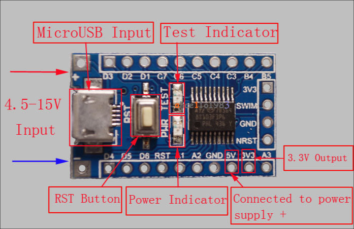

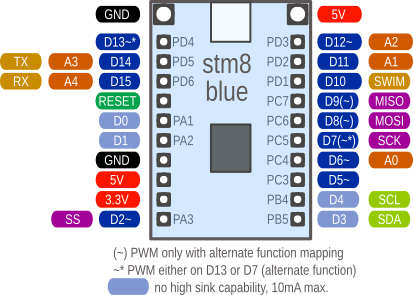
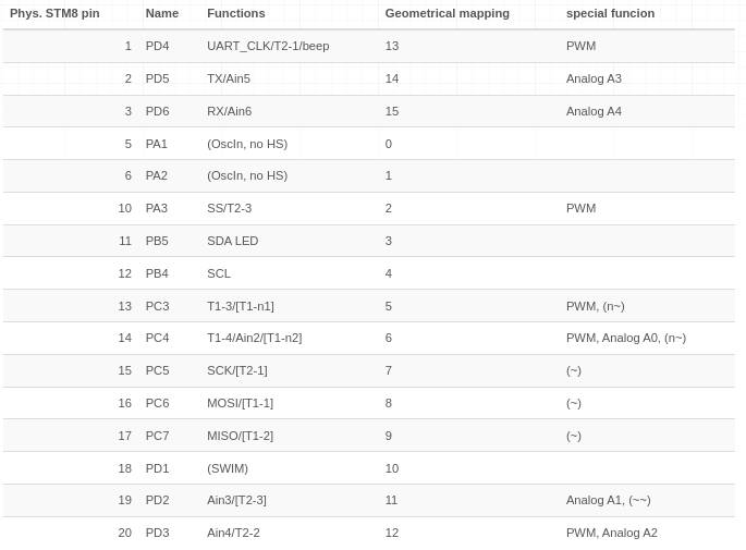
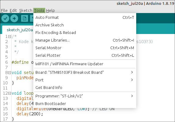
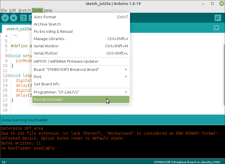
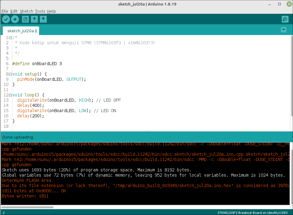

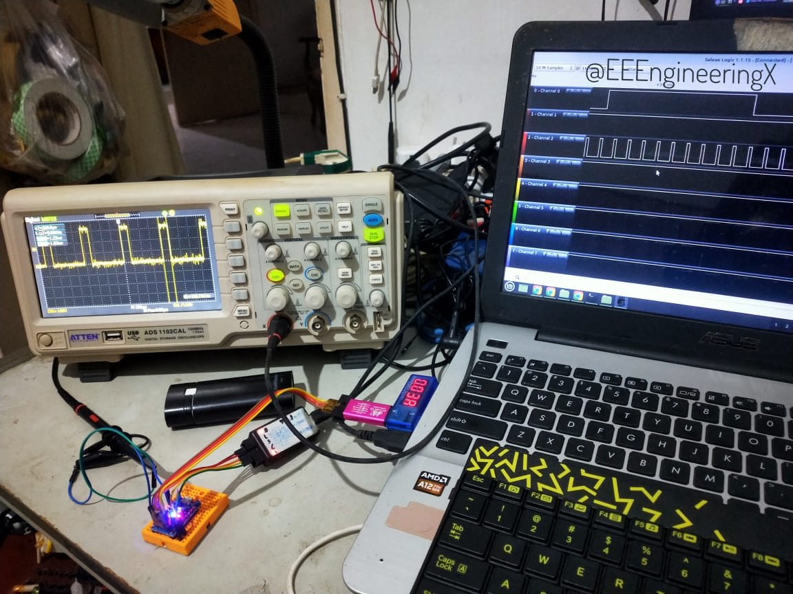
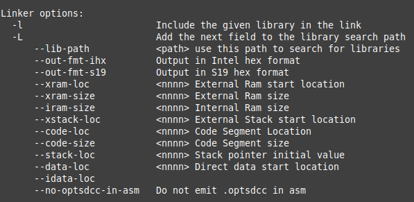
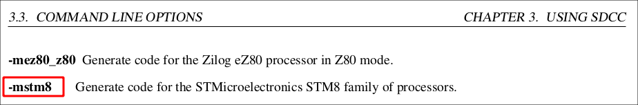
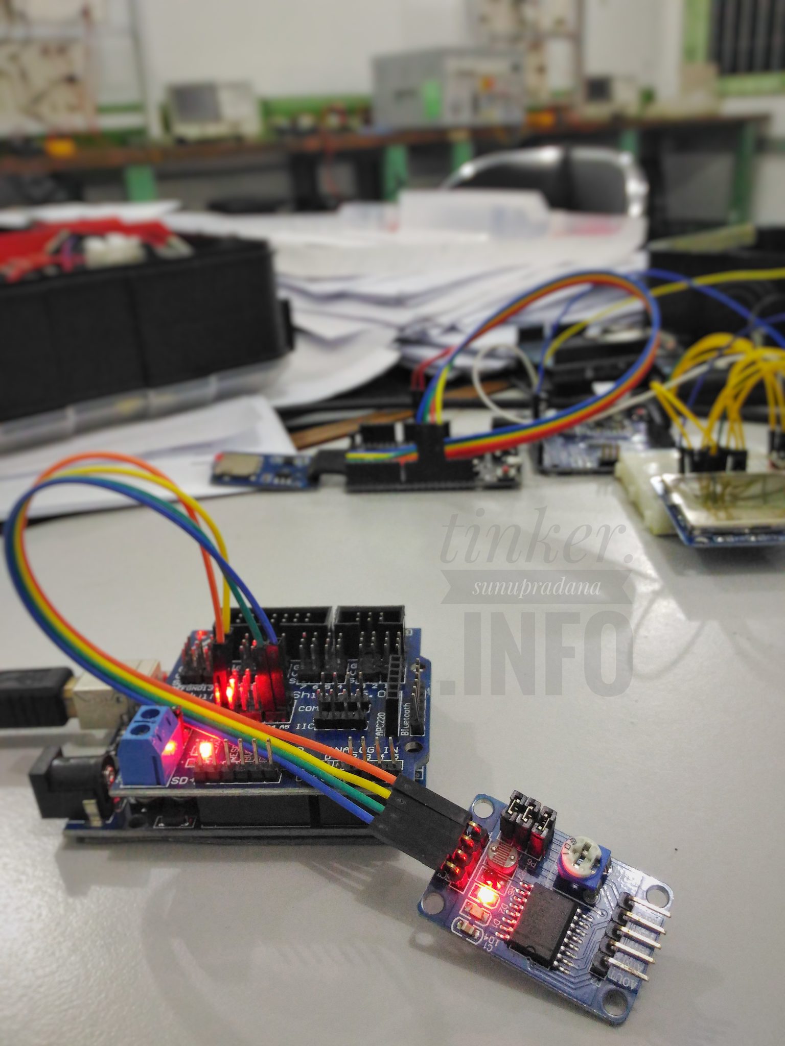
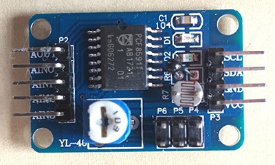 Gambar 2. [
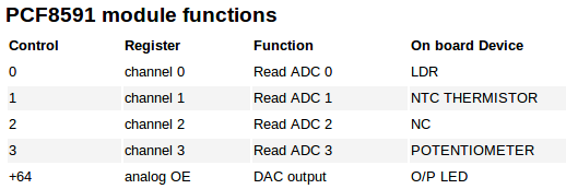 Gambar 3. [
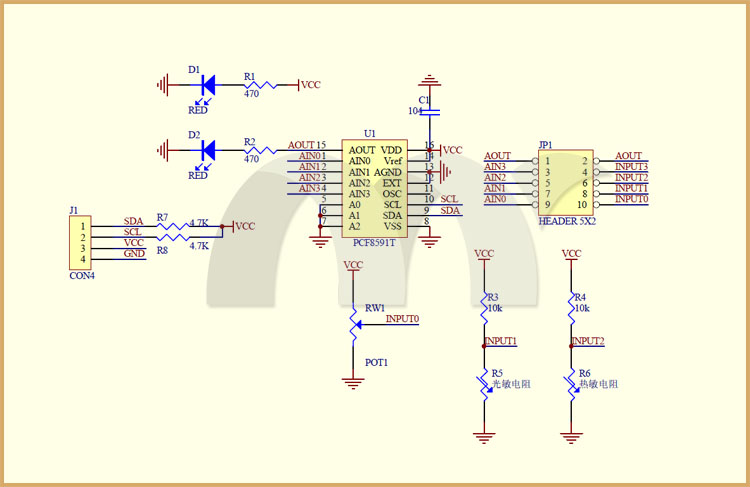 Gambar 5.[
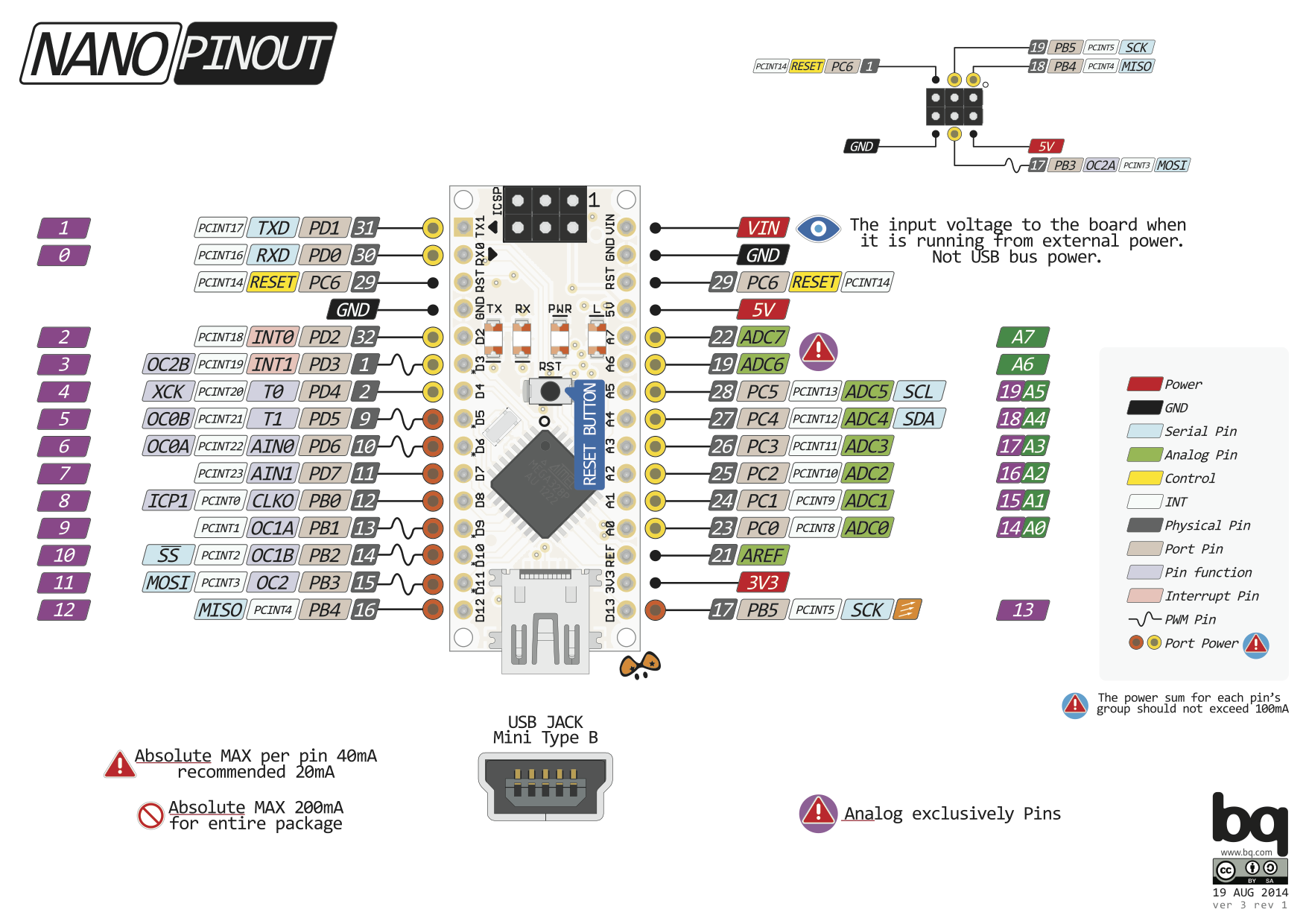


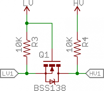 Gambar 1.
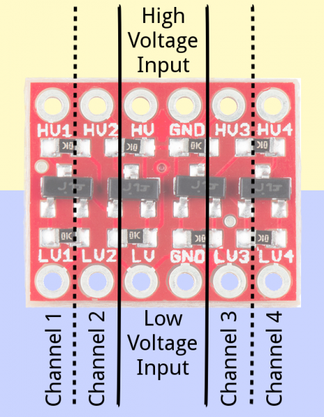 Gambar 2.
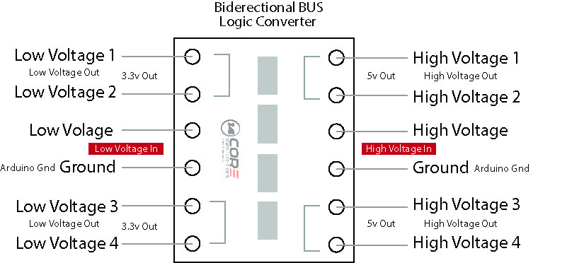 Gambar 3. [
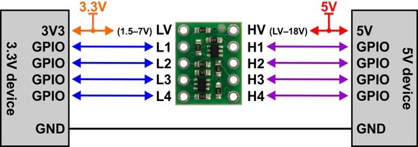 Gambar 4.
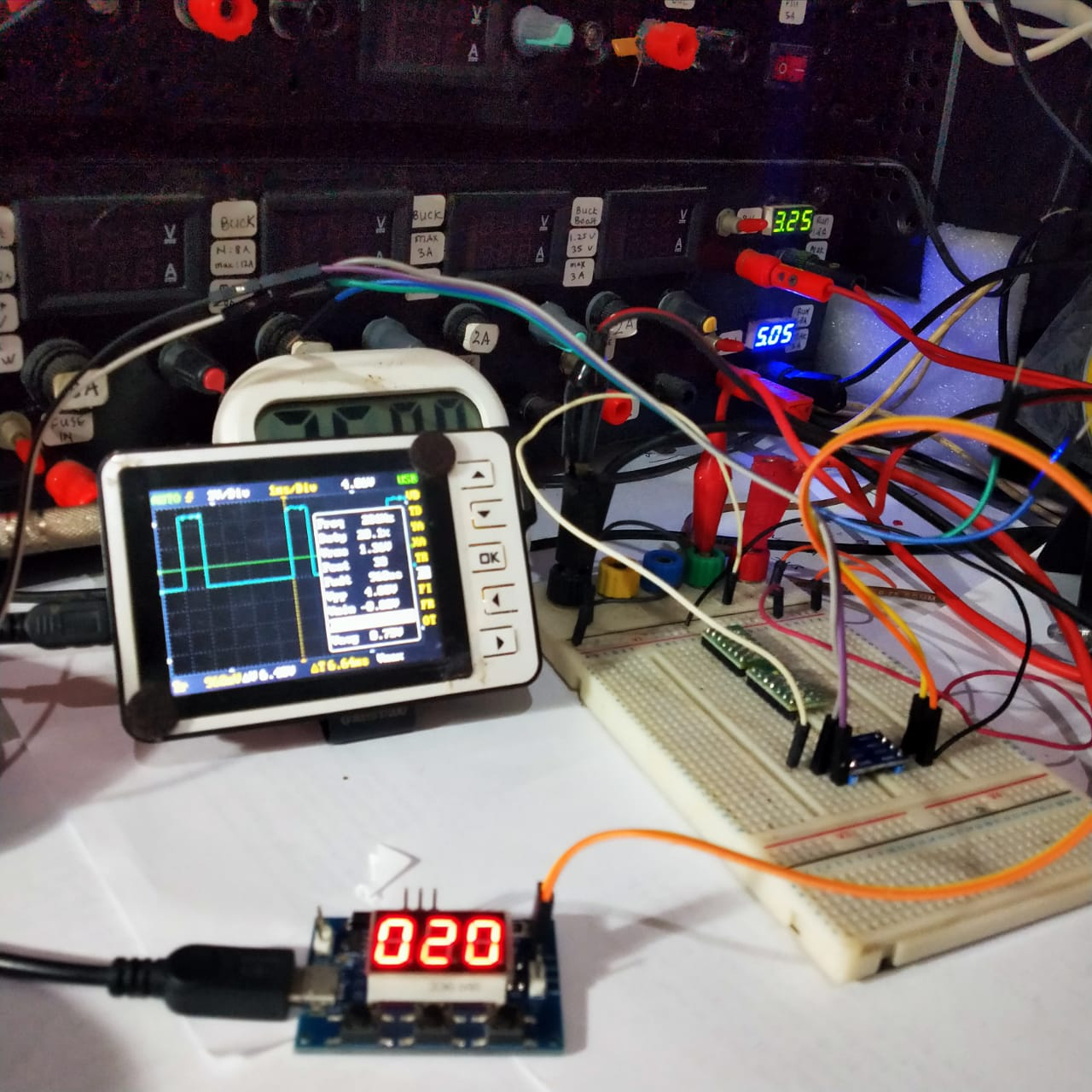 Gambar 6.

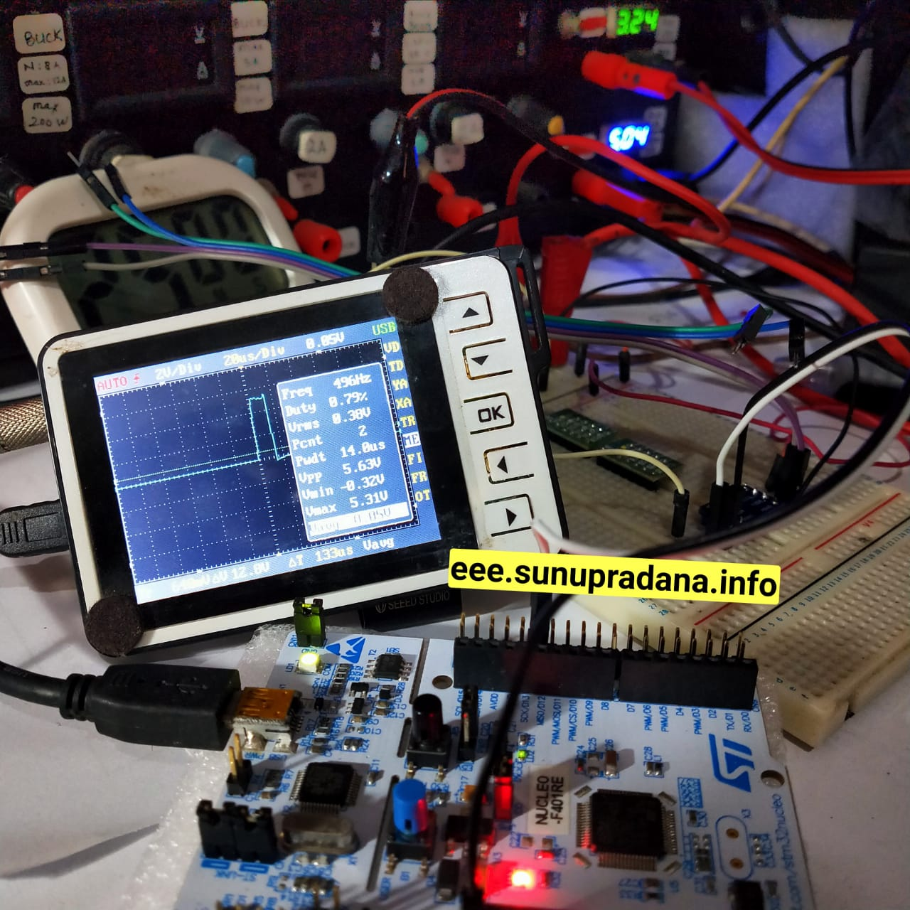 Gambar 9.
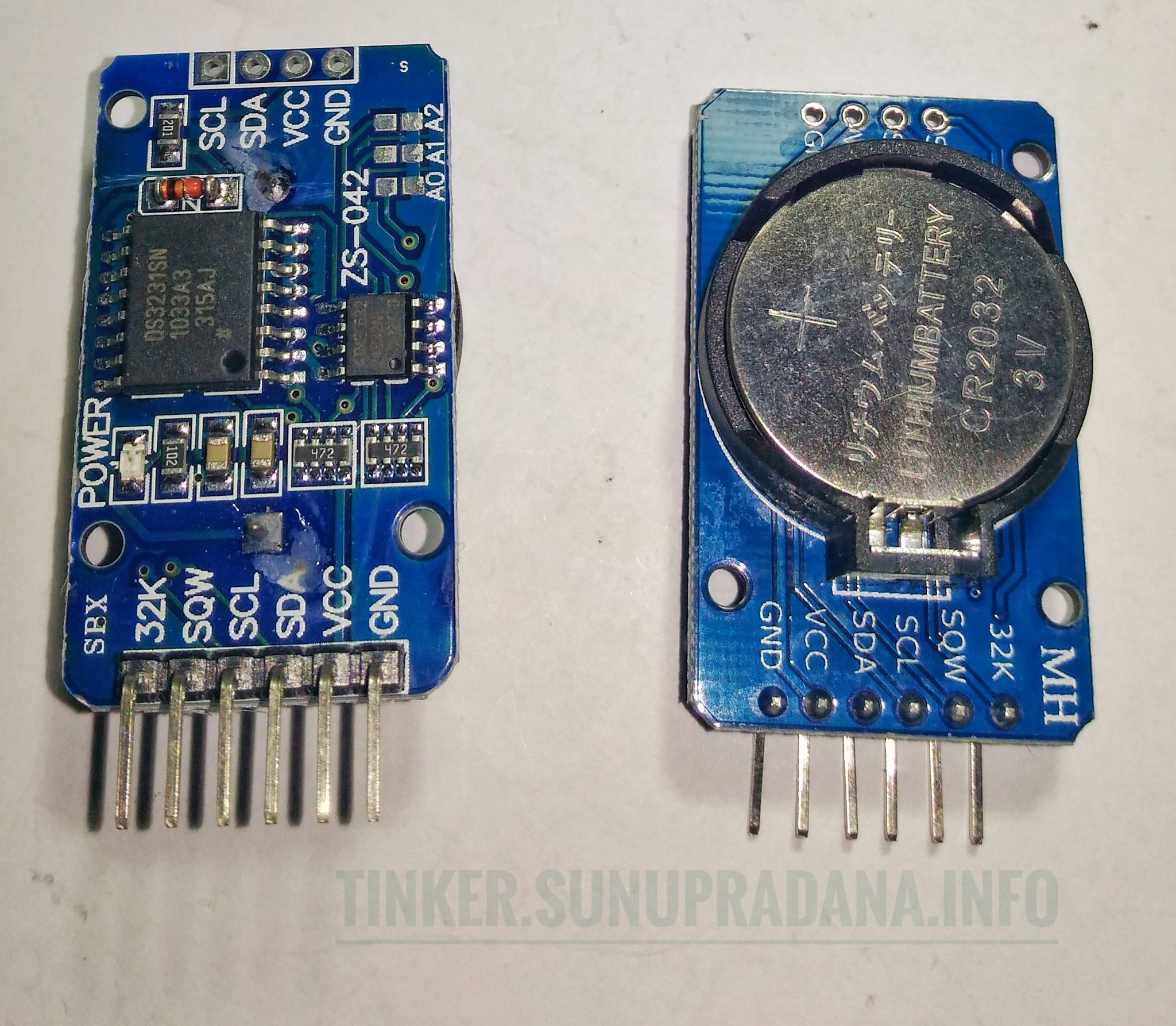
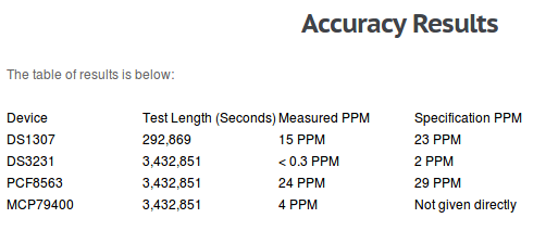
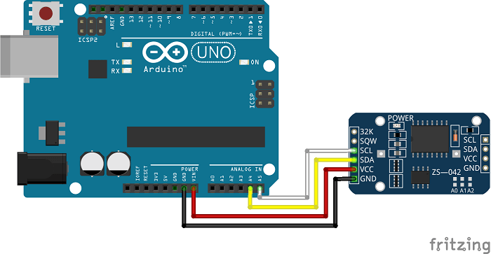 Gambar 2. [
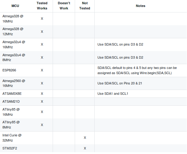
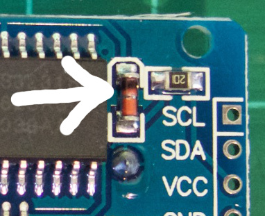 Gambar 3. [sumber:
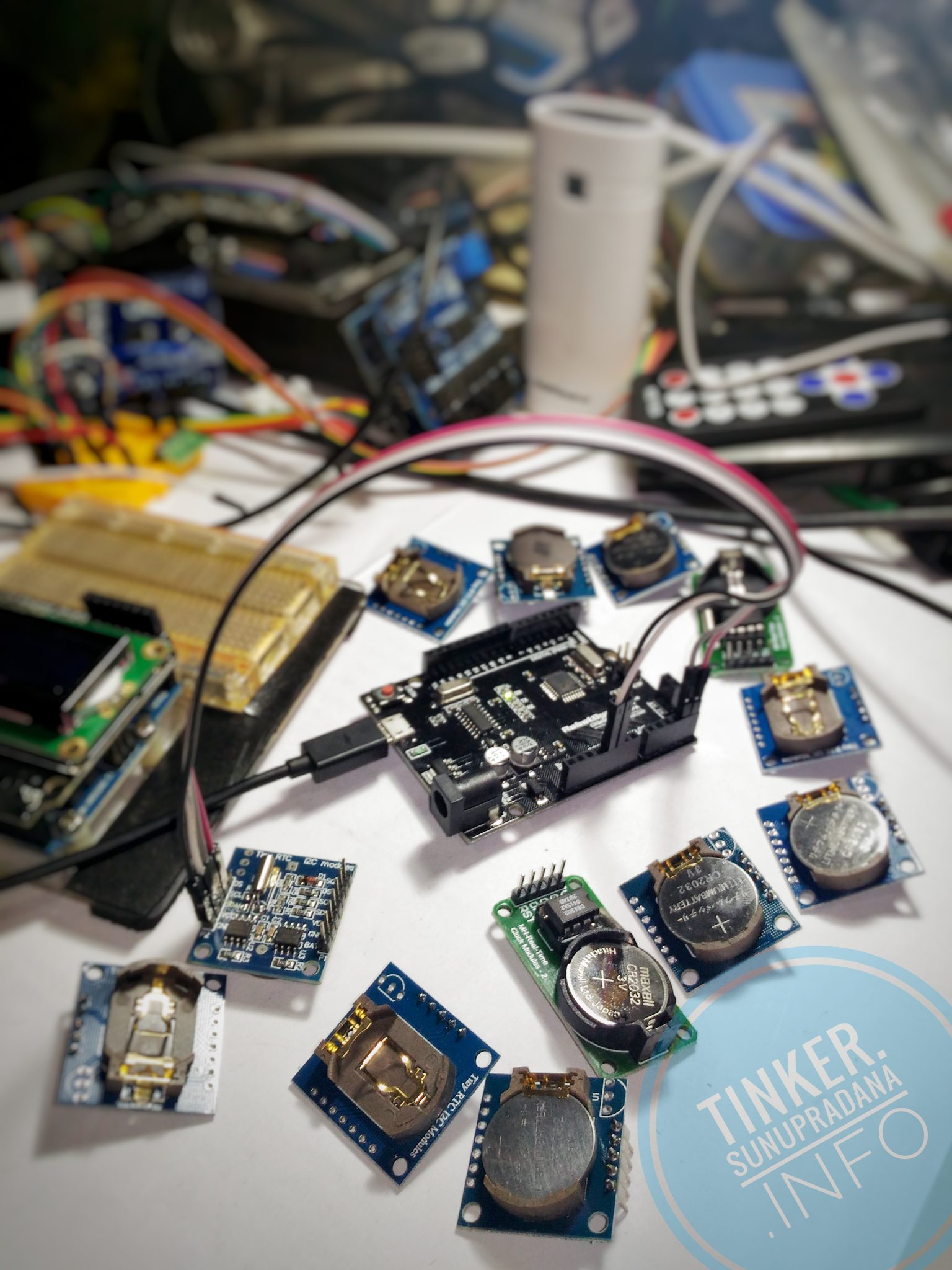
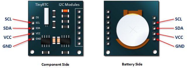
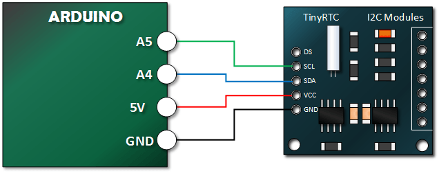
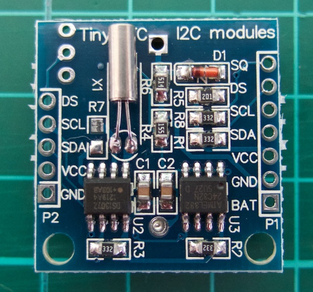 Gambar 4. [
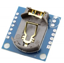 Gambar 5.
 Gambar 6.
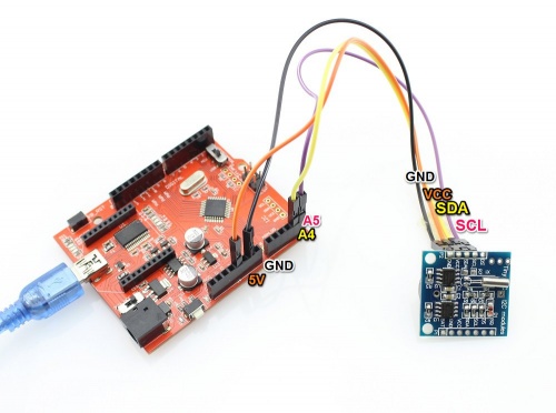 Gambar 7.
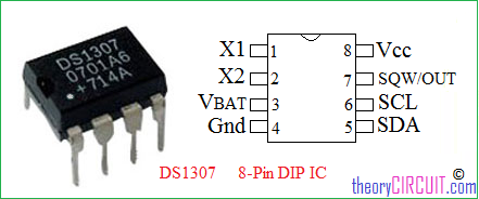 Gambar 8.
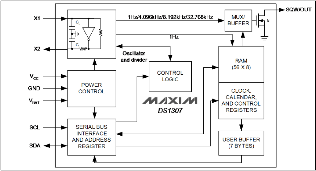 Gambar 9. [
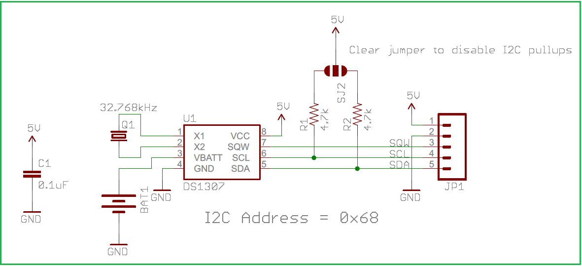 Gambar 10.
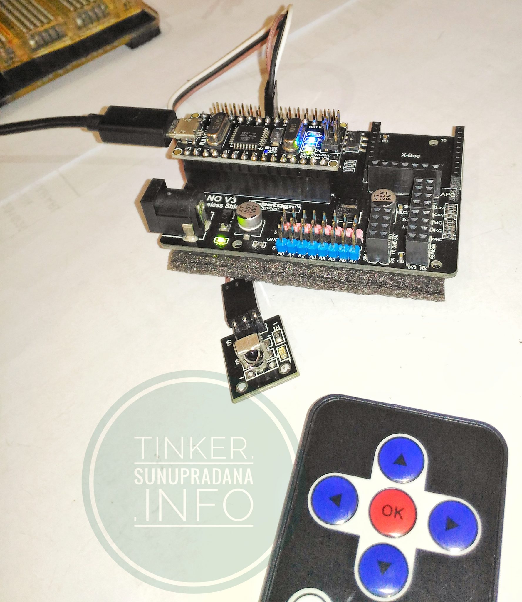
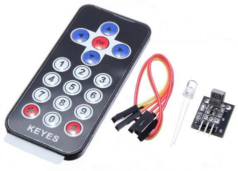 Gambar 1. [
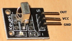 Gambar 2. [
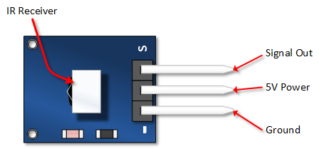 Gambar 3. [
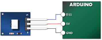 Gambar 4. [
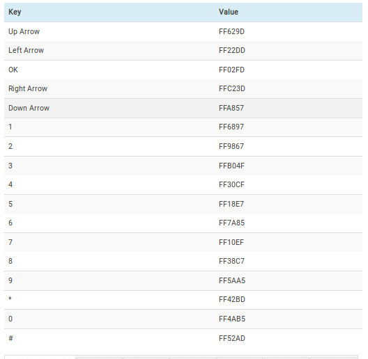
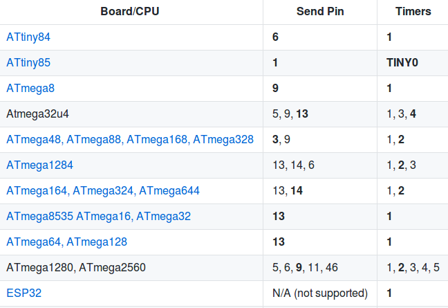

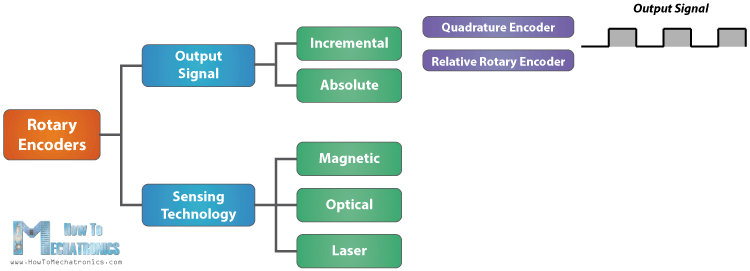 Gambar 2.
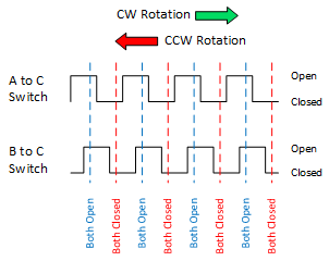
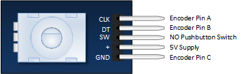
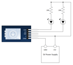
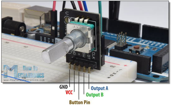 Gambar 11.
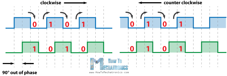 Gambar 13.
 Gambar 16.
 Gambar 17.
 Gambar 18.
 Gambar 19.
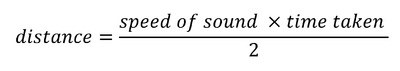

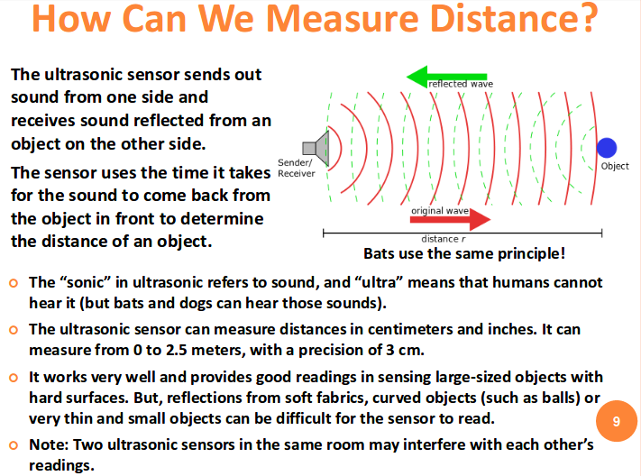 Gambar 5. [
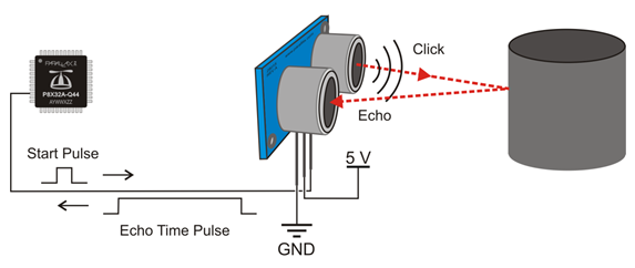 Gambar 10. [
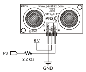 Gambar 11. [
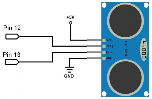 Gambar 13. [
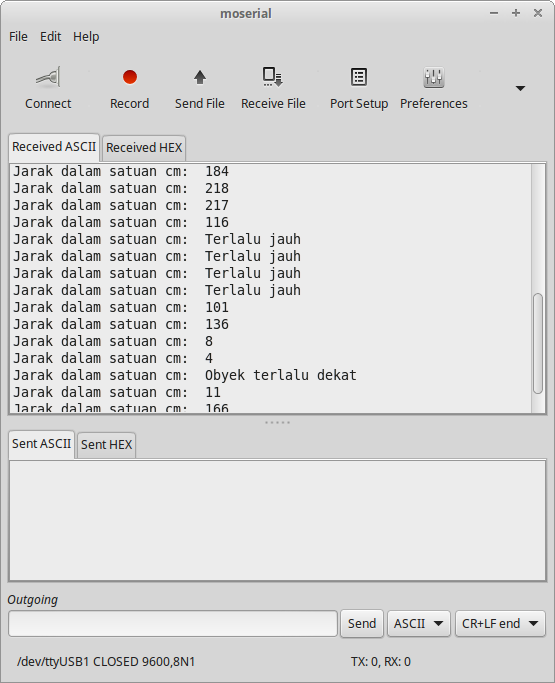 Gambar 16. Hasil pengukuran jarak
 Gambar 17.
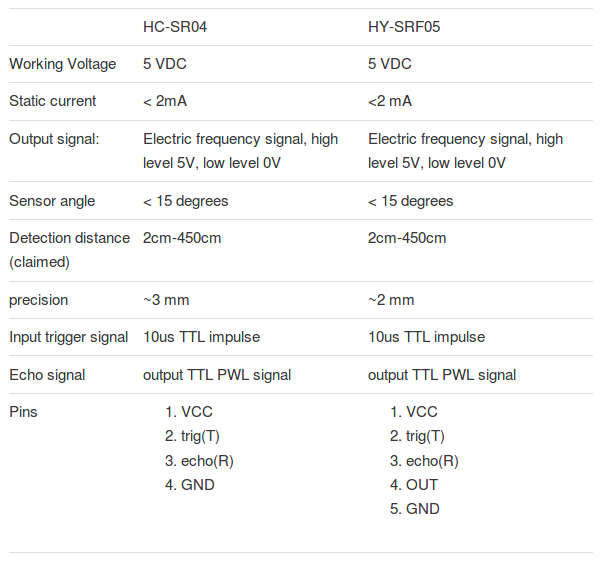
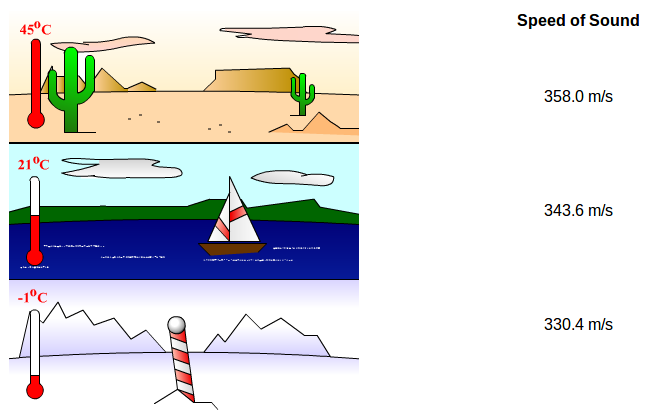 Gambar 19. [
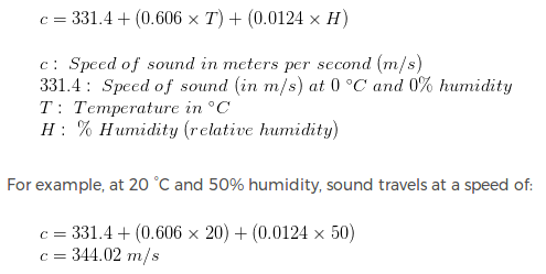
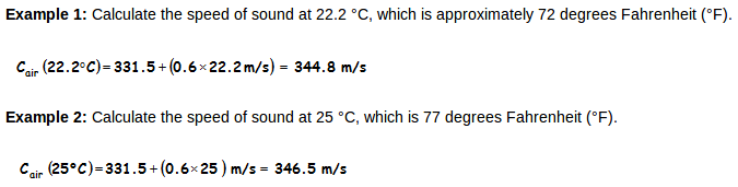

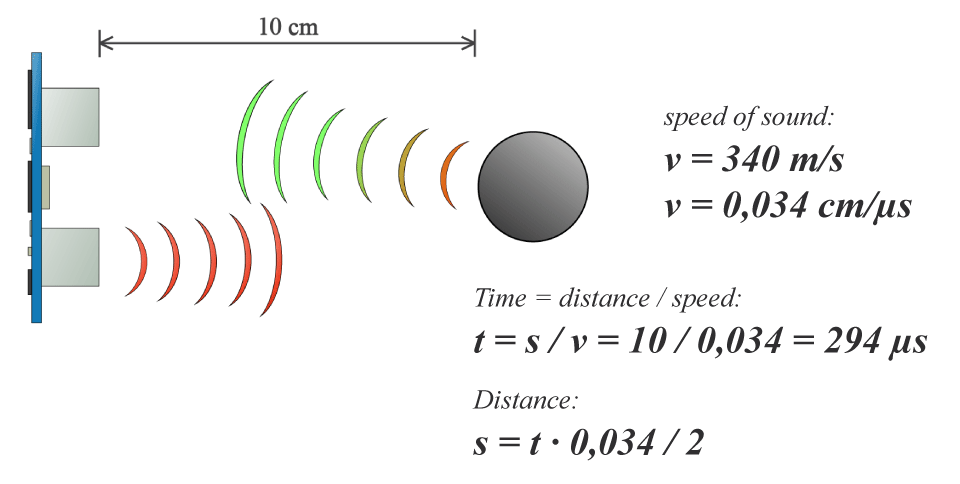
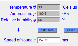 Gambar 20. [
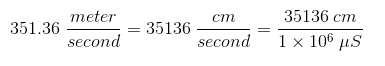
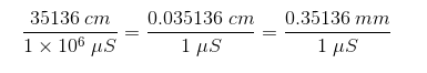

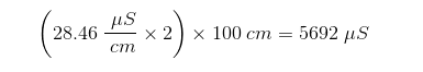
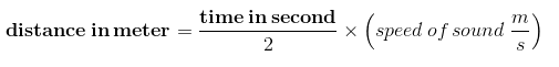
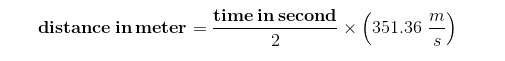
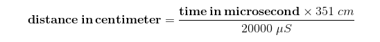
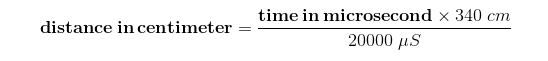
 Gambar 21. [
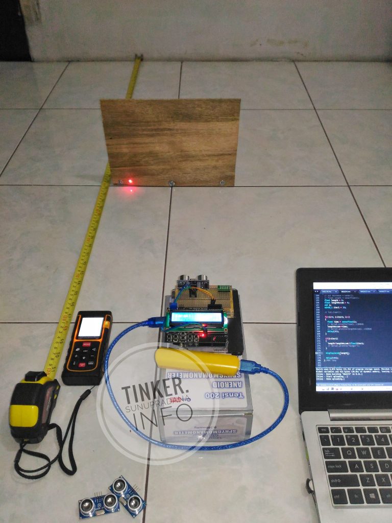
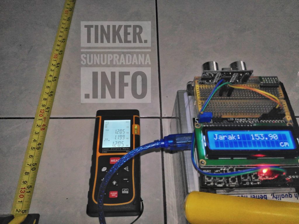
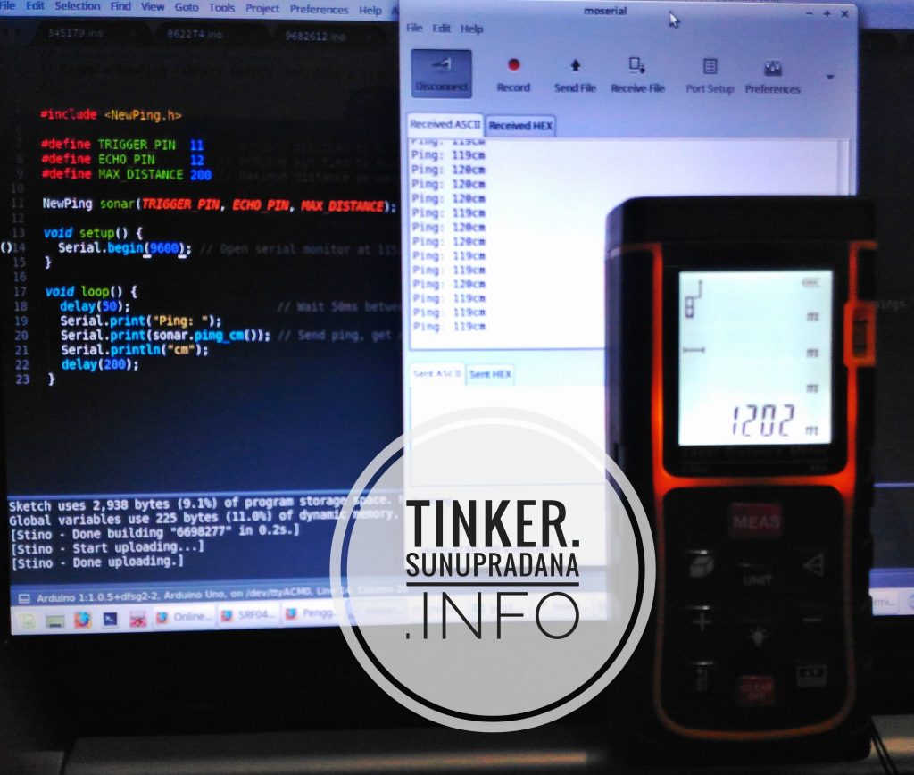
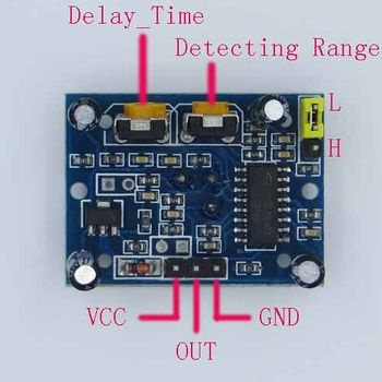 Gambar 6. [
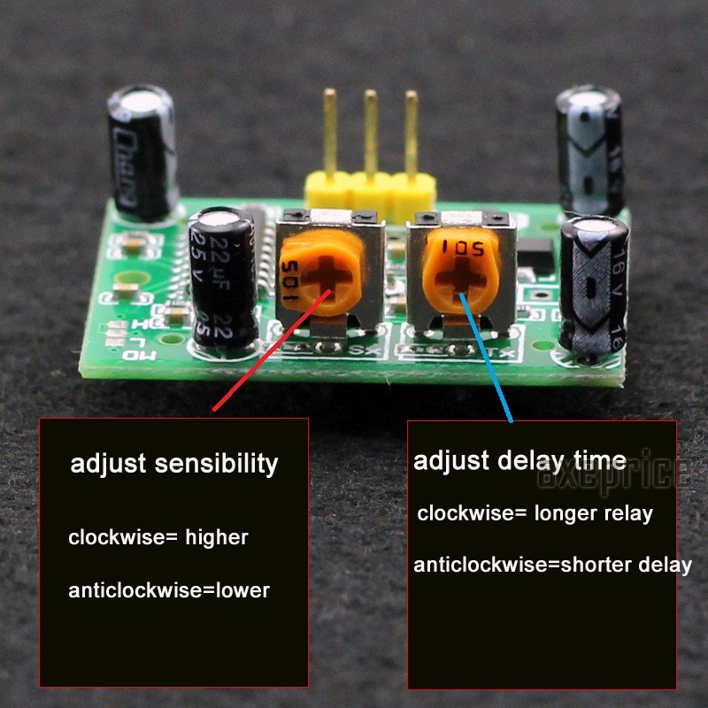 Gambar 9. [
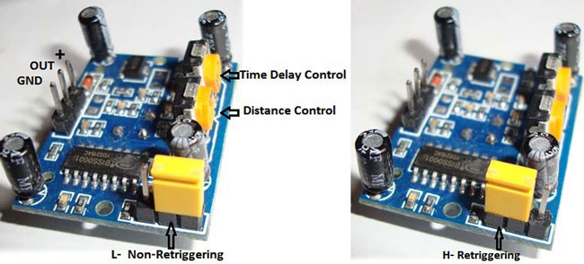 [Gambar 10.]
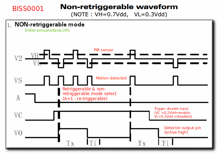
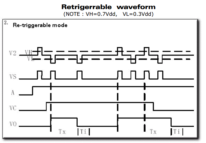
 Gambar 11. [