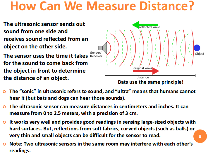
Sensor ultrasonic (ultrasonik) seperti srf04 dan srf05 dipergunakan untuk mengukur jarak suatu obyek.
Gambar 1. [sumber]
Gambar 2. [sumber]
As the name indicates, ultrasonic sensors measure distance by using ultrasonic waves.
The sensor head emits an ultrasonic wave and receives the wave reflected back from the target. Ultrasonic Sensors measure the distance to the target by measuring the time between the emission and reception.~http://www.keyence.com/ss/products/sensor/sensorbasics/ultrasonic/info/
What is ultrasound?
Ultrasound is basically normal sound waves with frequencies so high that they are inaudible to the human ear. Ultrasound can be used to measure distances to objects by measuring the delay between the transmission of an ultrasound pulse and the return of the echo. This is the well-known way bats navigate in the dark, and the same principles your ultrasonic grade sensor applies to measure the distance to a reference such as a string, a curb or the ground.
~http://tf-technologies.com/blog/what-ultrasound-and-how-does-ultrasonic-grade-sensor-work
Ultrasonic sensors (also known as transceivers when they both send and receive, but more generally called transducers) work on a principle similar to radar or sonar which evaluate attributes of a target by interpreting the echoes from radio or sound waves respectively. Ultrasonic sensors generate high frequency sound waves and evaluate the echo which is received back by the sensor. Sensors calculate the time interval between sending the signal and receiving the echo to determine the distance to an object.
This technology can be used for measuring wind speed and direction (anemometer), tank or channel level, and speed through air or water. For measuring speed or direction a device uses multiple detectors and calculates the speed from the relative distances to particulates in the air or water. To measure tank or channel level, the sensor measures the distance to the surface of the fluid. Further applications include: humidifiers, sonar, medical ultrasonography, burglar alarms and non-destructive testing.
Systems typically use a transducer which generates sound waves in the ultrasonic range, above 18,000 hertz, by turning electrical energy into sound, then upon receiving the echo turn the sound waves into electrical energy which can be measured and displayed.
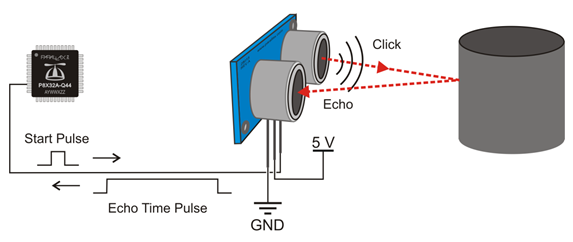
An Ultrasonic sensor is a device that can measure the distance to an object by using sound waves. It measures distance by sending out a sound wave at a specific frequency and listening for that sound wave to bounce back. By recording the elapsed time between the sound wave being generated and the sound wave bouncing back, it is possible to calculate the distance between the sonar sensor and the object.
[Gambar 3.]
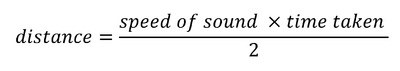
Since it is known that sound travels through air at about 344 m/s (1129 ft/s), you can take the time for the sound wave to return and multiply it by 344 meters (or 1129 feet) to find the total round-trip distance of the sound wave. Round-trip means that the sound wave traveled 2 times the distance to the object before it was detected by the sensor; it includes the ‘trip’ from the sonar sensor to the object AND the ‘trip’ from the object to the Ultrasonic sensor (after the sound wave bounced off the object). To find the distance to the object, simply divide the round-trip distance in half.
NOTE: The accuracy of Ultrasonic sensor can be affected by the temperature and humidity of the air it is being used in. However, for these tutorials and almost any project you will be using these sensors in, this change in accuracy will be negligible.
It is important to understand that some objects might not be detected by ultrasonic sensors. This is because some objects are shaped or positioned in such a way that the sound wave bounces off the object, but are deflected away from the Ultrasonic sensor. It is also possible for the object to be too small to reflect enough of the sound wave back to the sensor to be detected. Other objects can absorb the sound wave all together (cloth, carpeting, etc), which means that there is no way for the sensor to detect them accurately. These are important factors to consider when designing and programming a robot using an ultrasonic sensor.
~http://education.rec.ri.cmu.edu/content/electronics/boe/ultrasonic_sensor/1.html
How does an ultrasonic grade sensor work?
Ultrasonic grade sensors are equipped with an ultrasonic transducer that both generates pulses and receives the returning echoes of each pulse. When the ultrasonic waves emitted by the sensor meet the physical reference, they bounce back as an echo, which can be detected by the sensor. The time between a pulse is sent out and its echo is received is called the travelling time. Because we know the speed of sound, the sensor can use the measured travelling time to determine the distance to the reference.
It does that just like you would determine the travelled distance in a car by multiplying the time behind the wheel with the speed of the car. For example, we know that
1 hour driving x 10 miles per hour = 10 miles distance travelled
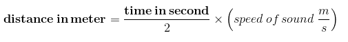
Driving time x speed = distanceFor the ultrasonic sensor, that means
Travelling time x speed of sound = distance to reference
When positioned on the screed on an asphalt paver, the grade sensor is able to maintain the desired asphalt thickness paved by ensuring that the distance to the reference remains the same. It does that by constantly checking the travelling time and calculating the distance to the reference to make sure it remains the same.
[Gambar 4.]
When a sensor is mounted to a paver and the screed starts to rise, the sensor will instantly detect an increase in travelling time and calculate the new increased distance to the reference. This prompts a message to the controller to start regulation of the tow point downwards, to bring the grade sensor back to its original distance above the reference to maintain the mat thickness.
This regulation happen instantaneously as the sensor is able to detect the change in travelling time much sooner than the naked eye can spot an increase in mat thickness. That is why the grade sensor is able to very precisely copy the reference, far beyond what is humanly possible, and place a mat at the required depth with millimeter precision.
Why do grade sensors need a reference bail?
As we just learned, when the travelling time and the speed of sound are known, then the sensor can determine the distance to the reference. The only challenge is that the speed of sound changes with different ambient temperatures. This poses a real challenge in asphalt paving, where temperature shifts can be huge due to factors such as changing wind directions and radiant heat.
As the grade sensor needs to know the current speed of sound to calculate the correct distance at all times, the grade sensor must overcome this obstacle and compensate for variations in temperature. It does that with a reference bail. The reference bail is used by the grade sensor to figure out the speed of sound by providing the sensor with a known distance from which the sensor can calculate the current speed of sound, based on the same formula used to calculate the distance to the reference. Brushing up on our math skills, we know that
Travelling time x speed = distance
can be rewritten to
Distance/travelling time = speed
Since the distance to the reference bail is known by the grade sensor, and it is able to measure the travelling time between the sensor and the reference bail, the sensor can calculate the speed of sound.
So, when the transducer sends out a pulse it actually receives two echoes: one from the reference bail and one from the physical reference. The first echo is used to calculate the current speed of sound and the second echo is used to determine the accurate distance to the reference.
In this way you can measure the accurate distance to the reference in various ambient temperatures, when you use a sonic sensor with a reference bail.

 Gambar 5. [sumber]
Gambar 6. [sumber]Gambar 7. [sumber] Gambar 8. [sumber]
Gambar 9. [sumber]
 Gambar 10. [sumber]
 Gambar 11. [sumber]
Gambar 12. [sumber]
 Gambar 13. [sumber]
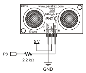
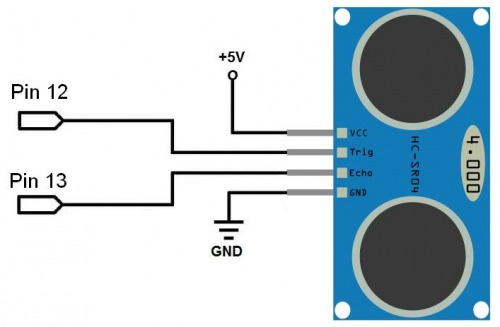
Hubungan ke pin pada Gambar 13 dapat diubah sesuai keperluan, tidak mutlak harus menggunakan pin 12 dan pin 13. Perhatikan perbedaan pin antara SR04/SRF04 dengan SR05/SRF05 seperti pada Gambar 14.
Gambar 14. [sumber] [/su_panel] [su_panel border=”3px solid #30C0F0″ radius=”10″]
Sebelum melanjutkan ke tahap yang lebih detail, bisa dicoba kode program yang relatif sederhana sebagai bahan untuk memahami proses kerja sensor lebih lanjut. Kode untuk SRF05 (jika menudukung) dengan menggunakan satu pin bisa dilihat di qqtrading.com.my.
Pengaturan mengikuti Gambar 14 (dua pin sinyal), dengan kode sederhana sebagai berikut:
[code lang=”C”] #define TRIG_PIN 7#define ECHO_PIN 6
const uint8_t BATAS_BAWAH = 4;
const uint16_t BATAS_ATAS = 300;
int sonar(void);
void setup()
{
Serial.begin(9600);
pinMode(ECHO_PIN, INPUT);
pinMode(TRIG_PIN, OUTPUT);
}
void loop()
{
int jarak = sonar();
Serial.print("Jarak dalam satuan cm: ");
// Serial.println( sonar() );
if(jarak<BATAS_BAWAH)
{
Serial.println("Obyek terlalu dekat");
}
else if(jarak>BATAS_ATAS)
{
Serial.println("Terlalu jauh");
}
else
{
Serial.println(jarak);
}
delay(1000);
}
int sonar(void)
{
digitalWrite(TRIG_PIN, HIGH);
delayMicroseconds(10);
digitalWrite(TRIG_PIN, LOW);
int jarak = pulseIn(ECHO_PIN, HIGH);
return (jarak = jarak / 58);
}
[/code]
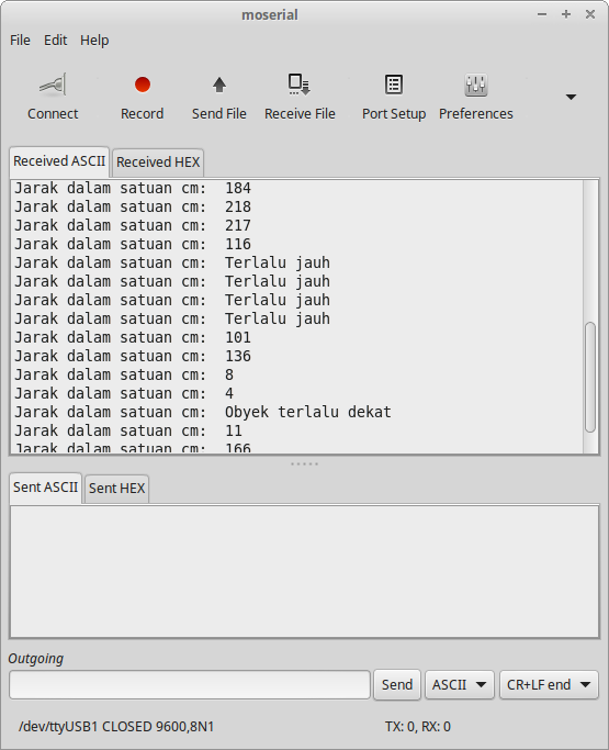 Gambar 16. Hasil pengukuran jarak
-
- Operating Voltage:5V
-
- Operating Frequency: 40Hz
-
- Max Range: 4m
-
- Min Range: 2cm
-
- Measuring Angle: 15 degree
-
- Trigger Input Signal: 10uS TTL pulse
-
- Echo Output Signal: TTL level signal, proportional to distance
 Gambar 17.
In operation, the processor waits for an active low trigger pulse to come in. It then generates just eight cycles of 40khz. The echo line is then raised to signal the host processor to start timing. The raising of the echo line also shuts of the MAX232. After a while – no more than 10-12mS normally, the returning echo will be detected and the PIC will lower the echo line. The width of this pulse represents the flight time of the sonic burst. If no echo is detected then it will automatically time out after about 30mS (Its two times the WDT period of the PIC). Because the MAX232 is shut down during echo detection, you must wait at least 10mS between measurement cycles for the +/- 10v to recharge. Performance of this design is, I think, quite good. It will reliably measure down to 3cm and will continue detecting down to 1cm or less but after 2-3cm the pulse width doesn’t get any smaller. Maximum range is a little over 3m. As and example of the sensitivity of this design, it will detect a 1inch thick plastic broom handle at 2.4m. Average current consumption is reasonable at less than 50mA and typically about 30mA. Calculating the Distance The SRF04 provides an echo pulse proportional to distance. If the width of the pulse is measured in uS, then dividing by 58 will give you the distance in cm, or dividing by 148 will give the distance in inches. uS/58=cm or uS/148=inches.
Changing beam pattern and beam width You can’t! This is a question which crops up regularly, however there is no easy way to reduce or change the beam width that I’m aware of. The beam pattern of the SRF04 is conical with the width of the beam being a function of the surface area of the transducers and is fixed. The beam pattern of the transducers used on the SRF04, taken from the manufacturers data sheet, is shown below.
Gambar 18.
SRF04 - Ultra-Sonic Ranger Technical SpecificationQ. What is the accuracy of the ranging? A. We quote 3-4cm. Its normally better than this, however so many factors affect accuracy that we won’t specify anything better than this. The speed of sound in air is approx. 346m/S at 24 degrees C. At 40KHz the wavelength is 8.65mm. The sonar’s detect the echo by listening for the returning wavefronts. This echo has an attack/decay envelope, which means it builds up to a peak then fades away. Depending on which wavefront is the 1st to be strong enough to be detected, which could be the 1st, 2nd or even 3rd, the result can jitter by this much. Another effect which limits accuracy is a phasing effect where the echo is not coming from a point source. Take a wall for example, the ping will bounce off the wall and return to the sonar. The wall is large, however, and there will be reflections from a large area, with reflections from the outside being slightly behind the central reflection. It is the sum of all reflections which the sensor sees which can be either strengthened or weakened by phasing effects. If the echo is weakened then it may be the following wavefront which is detected - resulting in 8.65mm of jitter. It is possible to see changes of distance as small as mm but then get cm of jitter. Q. What distance above the floor should the sonar be mounted? A. If you can mount the SRF04/8 12in/300mm above the floor, that should be OK. If you mount them lower, you may need to point them upwards slightly to avoid reflections from the carpet pile or ridges in a concrete floor. Q. What is the RH limit for the transducers? A. This is not specified by the transducer manufacturers and is not listed in the data sheet. The following is the manufacturers response to an email “The RH here in Taiwan is normally higher than 95%. Just if this sensor(400ST/R160) is used in the air, it should be okay. Don’t use in outdoors. Exposing in rainy day or underwater is not allowed.” Q. Can I fire two or more sonar’s at the same time? A. No! If two or more sonar’s are fired together then they could pick up each other “ping” resulting in a false readings. Fire them sequentially 65mS apart A. Yes! We do this all the time on our test robot, firing 8 SRF08’s at the same time. They are facing outwards and fitted around a 15inch diameter circle. The gain is set to minimum and they are fired using the I2C general call at address 0, and read individually at their set addresses. Under these circumstances there is no direct interference. A. Possibly! - Try it, and compare the results with firing them sequentially at 65mS intervals. Q. Can I change the sonar frequency of 40KHz to something else? A. No. The frequency must be 40KHz, because that is the only frequency the transducers will operate at. Also the circuitry is designed to operate at 40KHz so you cannot change the transducers to other frequency types. Q. What is the power output of the ultrasonic burst. A. On the SRF04, SRF08 and SRF10 its 100-150mW.
~http://www.robot-electronics.co.uk/htm/sonar_faq.htm
Introduction The SRF05 is an evolutionary step from the SRF04, and has been designed to increase flexibility, increase range, and to reduce costs still further. As such, the SRF05 is fully compatible with the SRF04. Range is increased from 3 meters to 4 meters. A new operating mode (tying the mode pin to ground) allows the SRF05 to use a single pin for both trigger and echo, thereby saving valuable pins on your controller. When the mode pin is left unconnected, the SRF05 operates with separate trigger and echo pins, like the SRF04. The SRF05 includes a small delay before the echo pulse to give slower controllers such as the Basic Stamp and Picaxe time to execute their pulse in commands. Mode 1 - SRF04 compatible - Separate Trigger and Echo This mode uses separate trigger and echo pins, and is the simplest mode to use. All code examples for the SRF04 will work for the SRF05 in this mode. To use this mode, just leave the mode pin unconnected - the SRF05 has an internal pull up resistor on this pin. Mode 2 - Single pin for both Trigger and Echo This mode uses a single pin for both Trigger and Echo signals, and is designed to save valuable pins on embedded controllers. To use this mode, connect the mode pin to the 0v Ground pin. The echo signal will appear on the same pin as the trigger signal. The SRF05 will not raise the echo line until 700uS after the end of the trigger signal. You have that long to turn the trigger pin around and make it an input and to have your pulse measuring code ready. The PULSIN command found on many popular controllers does this automatically.
~https://www.robot-electronics.co.uk/htm/srf05tech.htm
 Gambar 19. [sumber]
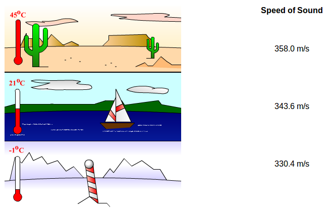
v = 331m/s + 0.6m/s/C * T
v is the speed of sound and T is the temperature of the air. One thing to keep in mind is that this formula finds the average speed of sound for any given temperature. The speed of sound is also affected by other factors such as humidity and air pressure. TEMPERATURE AND THE SPEED OF SOUND
Ultrasound and Microcontroller Applications Speed of Sound The nominal value for speed of sound in seawater is nominally 1500 m/s at about 13 degrees centigrade. At salinity level of 35 parts per thousand, depth 0 meters and temperature 0 degrees, speed of sound is 1449.3 m/s. Speed of sound in air is nominally 346m/s at 25 degrees, this speed drops to 331 at 0 degrees. The temperature dependency is second order given that other parameters are constant. Speed of sound in air (some applications using 40khz ultrasonic sensors) Speed of sound in air is mainly effected by temperature, humidity however has some effect. Temperature gradients in air and humidity effect the attenuation of sound, temperature whirlpools may refract the sound and to some effect reflect the impeding sound. Speed of sound as a function of temperature only:
c = 331,3 (m/s) * (1+T/273)1/2
c = 1087 (ft/s) * (1+T/273)1/2
T is temparture in centigrade C°
Sound Attenuation in Air Overall attenuation in air can be composed from the following: geometric spreading, conduction and shear viscosity losses, molecular relaxation, boundaries, refraction by non-homogeneous atmosphere, diffraction by turbulence. Atmospheric absorption is a function of distance and is effected by secondary factors like temperature, humidity and atmospheric pressure. Decibel variations in atmospheric attenuation due to secondary factors can be more than an order of magnitude. Most significant attenuation is due to relaxation or absorption of the medium. This attenuation for ultrasound apears to be mostly linear with respect to the decibel scale, and can be given in terms of db/ft or db/m.
a=0.01(db/ft) * f
a=0.033(db/m) * f
where: a is attenuation and f is frequency in terms of KHZ Geometric spreading depends on the transducer used, and is sensitive to the beam width.
~http://www.hexamite.com/hetheory.htm
Because the speed of sound depends on the density of the material, and the density depends on the temperature, there is a relationship between the temperature in a given medium and the speed of sound in the medium. For air at sea level, the speed of sound is given by
where the temperature in the first equation (denoted as TCTC) is in degrees Celsius and the temperature in the second equation (denoted as TKTK) is in kelvins. The speed of sound in gases is related to the average speed of particles in the gas, vrms=3kBTm,vrms=3kBTm, where kBkB is the Boltzmann constant (1.38×10⁻²³J/K)(1.38×10−23J/K) and m is the mass of each (identical) particle in the gas. Note that v refers to the speed of the coherent propagation of a disturbance (the wave), whereas vrmsvrms describes the speeds of particles in random directions. Thus, it is reasonable that the speed of sound in air and other gases should depend on the square root of temperature. While not negligible, this is not a strong dependence. At 0°C0°C, the speed of sound is 331 m/s, whereas at 20.0°C20.0°C, it is 343 m/s, less than a 4%4% increase.
~http://cnx.org/contents/C3iA05uy@4/Speed-of-Sound
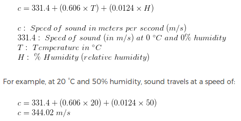
The approximate speed of sound in dry (0% humidity) air, in meters per second, at temperatures near 0 °C, can be calculated from
The value of 331.3 m/s, which represents the speed at 0 °C (or 273.15 K), is based on theoretical (and some measured) values of the heat capacity ratio, γ, as well as on the fact that at 1 atm real air is very well described by the ideal gas approximation. Commonly found values for the speed of sound at 0 °C may vary from 331.2 to 331.6 due to the assumptions made when it is calculated. If ideal gas γ is assumed to be 7/5 = 1.4 exactly, the 0 °C speed is calculated (see section below) to be 331.3 m/s, the coefficient used above. This equation is correct to a much wider temperature range, but still depends on the approximation of heat capacity ratio being independent of temperature, and for this reason will fail, particularly at higher temperatures. It gives good predictions in relatively dry, cold, low pressure conditions, such as the Earth’s stratosphere. The equation fails at extremely low pressures and short wavelengths, due to dependence on the assumption that the wavelength of the sound in the gas is much longer than the average mean free path between gas molecule collisions. A derivation of these equations will be given in the following section.
~https://en.wikipedia.org/wiki/Speed_of_sound
Knowing the time it takes the ultrasonic pulse to travel back and forth to the object, and also knowing the speed of sound, the Arduino can calculate the distance to the object. The formula relating the speed of sound, distance, and time traveled is:
In the equation above, it’s clear that temperature has the largest effect on the speed of sound. Humidity does have some influence, but it’s much less than the effect of temperature.
Environmental influences
Air temperature Air temperature has the greatest impact on the measuring accuracy of an ultrasonic sensor. After the transit time of the reflected ultrasonic pulse has been measured, the sensor calculates the distance to the object using the speed of the sound. However, as the air temperature changes, the speed of sound changes by 0.17% per degree Kelvin. Almost all Pepperl+Fuchs ultrasonic sensors have a temperature probe to compensate for this effect. This probe measures the ambient temperature and the sensor corrects the temperature-related distortion of the measured values (see temperature compensation). Humidity Humidity has negligible influence on the speed of sound at room temperature and at lower temperatures. However, at higher air temperatures, the speed of sound increases as humidity increases. Air pressure The speed of sound decreases by less than 1% between sea level and 3,000 m altitude. Atmospheric fluctuations at a specific location are negligible and the effects on the speed of sound are hardly measurable. Air currents If the object has the reflective properties of the standard reflector, regular air currents (wind) have no effect on ultrasonic measurement to speeds of 7 Bft (50-61.5 km/h). Stormy weather or hurricanes can cause unstable measurements (with loss of signal). Regarding changes to the speed of sound, no general conclusions can be drawn. This is because air current direction and air current speeds constantly change. For example, particularly hot objects, such as red-hot metal, cause significant air turbulence. The ultrasound can be scattered or deflected in such a way that no evaluable echo is returned. Paint mist Paint mist has no detectable effect on the operation of ultrasonic sensors. However, the mist should not be allowed to settle on the active transducer surface to avoid compromising the transducer’s sensitivity. External noise External noise is distinguished from the desired target echoes and generally does not cause malfunctions. If the source of disturbance has the same frequency as the ultrasonic sensor, the level of the external noise must not exceed the level of the target echoes. This can occur when filling a silo with stone, as an example. Types of gas Ultrasonic sensors by Pepperl+Fuchs are designed for operation in atmospheric air. Operation in other gases (for example in carbon dioxide) can cause serious errors of measurement or even total loss of function due to deviations in the speed of sound and attenuation.
Temperature compensation
Ultrasonic sensors operate using the echo transit time method, which means the time that is elapsed between the emitted ultrasonic pulse and when the received echo is evaluated. The ultrasonic sensor calculates the distance of the object from the speed of sound. When sound is propagated in air, the speed of sound is about 344 m/s at room temperature. However, the speed of sound is temperature-dependent and changes by approximately 0.17% with each degree Celsius. These changes affect the transit time and can distort the calculated distance. Most ultrasonic sensors by Pepperl+Fuchs have a working range of -25° C to +70° C. Without temperature compensation and at a measuring distance of 100 cm, a 20° C change in temperature would cause a measurement error of -8.5 cm at 70° C and +7.65 cm at -25° C. Therefore, most of these ultrasonic sensors are equipped with temperature probes whose measurements are used to correct the measured distances. This compensation is performed over the entire working range of the ultrasonic sensors from -25° C to +70° C and allows measurement accuracies of approximately ±1.5% to be achieved.
Accuracy
Accuracy/absolute accuracy refers to the difference between the output value that is measured by the ultrasonic sensor and the actual target distance. From a practical viewpoint, absolute accuracies of 1% to 3% are realistic in industrial applications for ultrasonic sensors in the operating range of -25° C to +70° C. Higher accuracies can be achieved in very stable ambient conditions. In this case, it is advisable to turn off temperature compensation (using the programming tool).
Another possibility would be to use an ultrasonic reference sensor. This approach involves mounting a second sensor of the same type parallel to the measuring sensor and aligning it to a fixed object. If ambient conditions in the measuring range change, the distance to the object will also appear to change due to the altered speed of sound. The measuring value must then be corrected by the value of this error.
~https://www.pepperl-fuchs.com/global/en/25518.htm
Below are examples for the speed of sound at two fairly comfortable, but slightly different indoor temperatures.
How does it work? The HC-SR04 ultrasonic sensor emits a train of ultrasonic waves with a membrane and receives the echo of these waves, when they bounce off objects, with another membrane. The operating principle is to the time of flight (TOF), which corresponds to the time that requires the ultrasonic wave to travel by air since it is generated until it is received. The distance travelled by the wave is indeed twice the distance of the ultrasound sensor to the object (is the distance to go and to return back). The sound speed in air is approximately 343.59 m/s, this means each 29uS the ultrasound wave travels a centimeter (58uS/cm to the object if we consider wave between the departure and the return time). The HC-SR04 sensor has (in addition to power supply VCC PIN to + 5V and 0V / GND mass) two pins controlling the trigger (TRIG) and the echo received by wave (ECHO). To generate a trigger, the TRIG should be active during at least 10uS (set to + 5V) and then set to 0V again. Then we must wait until the ECHO signal is active and measure the elapsed time between the trigger and the echo. To calculate the distance of the object in centimeters, we divide time into uS by 58.
Distance Calculations
- Time = Width of Echo pulse, in uS (micro second)
- Distance in centimeters = Time / 58
- Distance in inches = Time / 148
The pulse width of the echo is proportional to the distance to an object. The data sheet indicates that the pulse width should be divided by 58 to obtain the distance in cm. To understand why this number is a correct approximation, we have the following derivation.
The speed of sound in dry air is calculated as
Velocity of sound in air = 331.4 + 0.6 x Celsius temperature (units, m/s)
At 20o C (68o F), it is 343.4 meters per second (1126.6 feet per second).
The distance accurately measured by this sensor ranges from 2 cm to 400 cm and the period of the pulse width is in microseconds. The formula to convert the pulse width to distance is as follows:
(343.4 m / sec) x (1 sec/10^6 microseconds) x (100 cm/1 m) x measured pulse width in microseconds = 2 x distance traveled in centimeters
The above relationship represents the total distance the sound pulse traveled. The total time measured is the time it took for the pulse to reach the object and travel back to the receiver. Rearranging the equation to calculate distance from sonar to object:
(343.4 m/1 s) x (1 s/10^6 micro sec) x (100 cm/ 1 m) x pulse width / 2 = distance to object (cm)
0.01717 x pulse width (microsec) = distance to object (cm)
The number 0.01717 can also be represented as 1/58.24, changing the formula to
pulse width (microsec)/58.24 = distance to object (cm)
We now know why the data sheet instructs us to divide the echo pulse width period by 58 to obtain the centimeter distance to the object.
To convert the pulse width to inches, use the conversion factor of 3.28084 ft = 1 meter. This results in dividing the pulse width by 147.9.
~http://www.ucdrobotics.org/?page_id=628
Ultrasonic distance sensors can find the range out to 2-4 meters and are popular in e.g. robotics. Here I look at how the accuracy can be improved by compensating for the variation of speed of sound with temperature. It actually varies quite a lot in air and around 0 C it is: c = 331.3 + 0.606 * T where c is in m/s and T is in C. The formula is good to up to at least +/-30 C. There is also a dependence of humidity, but as it is so small it is neglected here. The equation can be analyzed for sensitivity (a little bit of differentation, you know). The result is that a two-way range measurement creates an error of 1.8 mm/C/m. That means that with a 4 degree C error, the deviation will be 14.4 mm at a range of 2 meters. Not a lot, but more than the wavelength which is 9 mm at 40 kHz. Considering how easy it is to compensate for, then why not give it a try? I have tested this with the inexpensive HC-SR04, but the compensation is really independent of the type of sensor. First let me analyze a typical example code for this sensor:
For range in cm the code divides elapsed time in microseconds by 29. That corresponds to c=10,000/29=344.8 m/s. According to the equation above, this is the speed for a temperature of 22.3 C.long microsecondsToCentimeters(long microseconds) { // The speed of sound is 340 m/s or 29 microseconds per centimeter. // The ping travels out and back, so to find the distance of the // object we take half of the distance travelled. return microseconds / 29 / 2; } Distance sensing with ultrasonic sensor and Arduino
if (FIXEDSPEED == 1) {c = 10000.0/29; // Original value for c in code} else {c = 331.3 + 0.606*Tc_100/100;}
float microsecondsToCentimeters(long microseconds, float c) { // The speed of sound is 340 m/s or 29 microseconds per centimeter. // — actually 29 microsec/cm = 10000/29 = 344.8 m/s, ie 22.3 deg C // The ping travels out and back, so to find the distance of the // object we take half of the distance travelled. return microseconds * c / 20000; }
Did You Know?
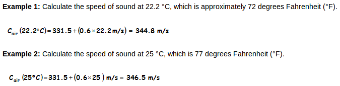
The ping library measures the echo pulse in terms of microseconds and then uses the fact that sound travels at 0.03448 cm/µs at room temperature. That’s 3.448 hundredths of a centimeter per millionth of a second at a temperature of (22.2 ºC). Just as a car travels distance = speed x time, so does sound, with an equation of s = ct, where s is the distance, c is the speed of sound and t is the time.

For example, if the object is 10 cm away from the sensor, and the speed of the sound is 340 m/s or 0.034 cm/µs the sound wave will need to travel about 294 u seconds. But what you will get from the Echo pin will be double that number because the sound wave needs to travel forward and bounce backward. So in order to get the distance in cm we need to multiply the received travel time value from the echo pin by 0.034 and divide it by 2.
 Gambar 20. [sumber]
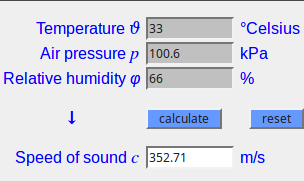
Sebagai catatan, situs penyedia layanan (sengpielaudio.com) di halaman tersebut mencantumkan bahwa perhitungan hanya dijamin akurat sampai suhu 30° C saja. Nilai pada Gambar 20 hanya sebagai perbandingan. Jika suhu diturunkan menjadi 30° C maka berdasarkan perhitungan di halaman itu kecepatan suara menjadi 350.7 m/s.
Dari semua bahan di atas dapat disarikan beberapa perhitungan yang berguna untuk memahami dan mengerjakan sistem dengan sensor ultrasonik. Pertama, mencari pendekatan terhadap nilai kecepatan suara (speed of sound).
c : Kecepatan suara (speed of sound) dalam satuan meter per second (m/S) 331.3 : Nilai speed of sound (dalam m/s) pada suhu 0° C dan 0% humidity T : Suhu (temperatur) dalam ° C H : % Humidity (relative humidity)
Jika memiliki sensor suhu dan kelembapan di sistem/papan mikrokontroler maka nilai c ini dapat dihitung saat kode program dieksekusi.
Sebagai contoh untuk beberapa nilai suhu dan nilai persen kelembapan relatif, dibuat tabel berikut:
Tabel hasil render QuickLaTeX.com:
[latex mode=1] \begin{table}[] \centering \begin{tabular}{|c|r|r|r|} \hline No & \multicolumn{1}{c|}{T} & \multicolumn{1}{c|}{H} & \multicolumn{1}{c|}{c} \\ \hline 1 & 20 & 50 & 343.834623 \\ \hline 2 & 27 & 75 & 348.218184 \\ \hline 3 & 30 & 72 & 349.912242 \\ \hline 4 & \multicolumn{1}{l|}{30} & \multicolumn{1}{l|}{66} & \multicolumn{1}{l|}{349.837842} \\ \hline 5 & \multicolumn{1}{l|}{33} & \multicolumn{1}{l|}{50} & \multicolumn{1}{l|}{351.362154} \\ \hline \end{tabular} \end{table} [/latex]
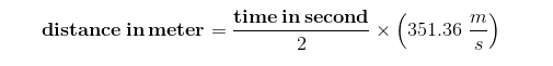
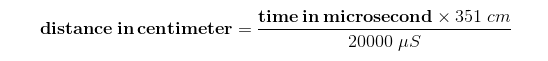
Berdasarkan tabel di atas jika nilai c diambil senilai 351.36 m/s maka nilai ini sama artinya dengan
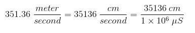
Untuk mencari berapa jarak yang ditempuh (menggunakan nilai c yang sama) selama 1 μS:
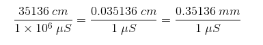
Untuk mencari berapa waktu yang diperlukan (menggunakan nilai c yang sama) untuk menempuh 1 cm:

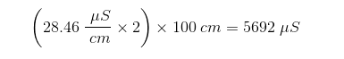
Jika menggunakan nilai 28.46 uS/cm maka untuk jarak 100 cm diperlukan waktu 2846 μS. Tetapi perlu diingat untuk penggunaan sensor ultrasonik, pengukuran dilakukan untuk waktu pengiriman dan waktu pantulan terdeteksi kembali. Jadi untuk obyek yang berjarak 100 cm, pengukuran dilakukan untuk 200 cm (100 cm untuk waktu pengiriman dan ditambah 100 cm untuk waktu pantulan). Perhitungannya menjadi:
Skenario berikutya adalah jika waktu tempuh yang diukur menggunakan sensor ultrasonik diketahui. Misalnya terukur waktu tempuh sebesar 1138 μS, berapakah jarak obyek di depan sensor ultrasonik?
Waktu yang ditempuh adalah untuk jarak sekitar 40 cm, tetapi ini waktu untuk “berangkat + pulang” sinyal ultrasonik. Bisa dilihat dari perhitungan, jarak obyek adalah separuhnya yang artinya dalam hal ini adalah sekitar 20 cm.
Beberapa artikel dan kode menggunakan langkah yang nampak sedikit berbeda untuk menentukan jarak obyek di depan sensor ultrasonik, walaupun jika diperhatikan sebenarnya sama saja. Berikut keterangan untuk memudahkan:
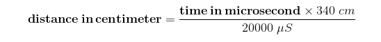
Beberapa orang melakukan pembulatan untuk efisiensi perhitungan, misalnya:
Jika menggunakan speed of sound yang berbeda, beberapa orang menuliskan persamaan sebagai berikut:
Description
Reads a pulse (either HIGH or LOW) on a pin. For example, if value is HIGH, pulseIn() waits for the pin to go HIGH, starts timing, then waits for the pin to go LOW and stops timing. Returns the length of the pulse in microseconds or 0 if no complete pulse was received within the timeout. The timing of this function has been determined empirically and will probably show errors in shorter pulses. Works on pulses from 10 microseconds to 3 minutes in length. Please also note that if the pin is already high when the function is called, it will wait for the pin to go LOW and then HIGH before it starts counting. This routine can be used only if interrupts are activated. Furthermore the highest resolution is obtained with short intervals.
Syntax
pulseIn(pin, value) pulseIn(pin, value, timeout)
Parameters
pin: the number of the pin on which you want to read the pulse. (int) value: type of pulse to read: either HIGH or LOW. (int) timeout (optional): the number of microseconds to wait for the pulse to be completed: the function returns 0 if no complete pulse was received within the timeout. Default is one second (unsigned long).
Returns
the length of the pulse (in microseconds) or 0 if no pulse is completed before the timeout (unsigned long) pulseIn()
#define trigPin 12
#define echoPin 13
void setup() {
  Serial.begin (9600);
  pinMode(trigPin, OUTPUT);
  pinMode(echoPin, INPUT);
}
void loop() {
  int duration, distance;
  digitalWrite(trigPin, HIGH);
  delayMicroseconds(1000);
  digitalWrite(trigPin, LOW);
  duration = pulseIn(echoPin, HIGH);
  distance = (duration/2) / 29.1;
  if (distance >= 200 || distance <= 0){
    Serial.println("Out of range");
  }
  else {
    Serial.print(distance);
    Serial.println(" cm");
  }
  delay(150);
}
http://howtomechatronics.com/tutorials/arduino/ultrasonic-sensor-hc-sr04/
/*
* Ultrasonic Sensor HC-SR04 and Arduino Tutorial
*
* Crated by Dejan Nedelkovski,
* www.HowToMechatronics.com
*
*/
// defines pins numbers
const int trigPin = 9;
const int echoPin = 10;
// defines variables
long duration;
int distance;
void setup() {
pinMode(trigPin, OUTPUT); // Sets the trigPin as an Output
pinMode(echoPin, INPUT); // Sets the echoPin as an Input
Serial.begin(9600); // Starts the serial communication
}
void loop() {
// Clears the trigPin
digitalWrite(trigPin, LOW);
delayMicroseconds(2);
// Sets the trigPin on HIGH state for 10 micro seconds
digitalWrite(trigPin, HIGH);
delayMicroseconds(10);
digitalWrite(trigPin, LOW);
// Reads the echoPin, returns the sound wave travel time in microseconds
duration = pulseIn(echoPin, HIGH);
// Calculating the distance
distance= duration*0.034/2;
// Prints the distance on the Serial Monitor
Serial.print("Distance: ");
Serial.println(distance);
}
If you want to display the results from the HC-SR04 Ultrasonic Sensor on an LCD you can use the following source code:
    /*
    * Ultrasonic Sensor HC-SR04 and Arduino Tutorial
    *
    * Crated by Dejan Nedelkovski,
    * www.HowToMechatronics.com
    *
    */
    #include <LiquidCrystal.h> // includes the LiquidCrystal Library
    LiquidCrystal lcd(1, 2, 4, 5, 6, 7); // Creates an LCD object. Parameters: (rs, enable, d4, d5, d6, d7)
    const int trigPin = 9;
    const int echoPin = 10;
    long duration;
    int distanceCm, distanceInch;
    void setup() {
    lcd.begin(16,2); // Initializes the interface to the LCD screen, and specifies the dimensions (width and height) of the display
    pinMode(trigPin, OUTPUT);
    pinMode(echoPin, INPUT);
    }
    void loop() {
    digitalWrite(trigPin, LOW);
    delayMicroseconds(2);
    digitalWrite(trigPin, HIGH);
    delayMicroseconds(10);
    digitalWrite(trigPin, LOW);
    duration = pulseIn(echoPin, HIGH);
    distanceCm= duration*0.034/2;
    distanceInch = duration*0.0133/2;
    lcd.setCursor(0,0); // Sets the location at which subsequent text written to the LCD will be displayed
    lcd.print("Distance: "); // Prints string "Distance" on the LCD
    lcd.print(distanceCm); // Prints the distance value from the sensor
    lcd.print(" cm");
    delay(10);
    lcd.setCursor(0,1);
    lcd.print("Distance: ");
    lcd.print(distanceInch);
    lcd.print(" inch");
    delay(10);
    }
http://arduino-info.wikispaces.com/UltraSonicDistance
/* YourDuino SKETCH UltraSonic Serial 2.0
 Runs HC-04 and SRF-06 and other Ultrasonic Modules
 Open Serial Monitor to see results
 Reference: http://playground.arduino.cc/Code/NewPing
 Questions?  [email protected] */
/*-----( Import needed libraries )-----*/
#include <NewPing.h>
/*-----( Declare Constants and Pin Numbers )-----*/
#define  TRIGGER_PIN  11
#define  ECHO_PIN     10
#define MAX_DISTANCE 200 // Maximum distance we want to ping for (in centimeters).
                         //Maximum sensor distance is rated at 400-500cm.
/*-----( Declare objects )-----*/
NewPing sonar(TRIGGER_PIN, ECHO_PIN, MAX_DISTANCE); // NewPing setup of pins and maximum distance.
/*-----( Declare Variables )-----*/
int DistanceIn;
int DistanceCm;
void setup()   /****** SETUP: RUNS ONCE ******/
{
  Serial.begin(9600);
  Serial.println("UltraSonic Distance Measurement");
  Serial.println("YourDuino.com  [email protected]");
}//--(end setup )---
void loop()   /****** LOOP: RUNS CONSTANTLY ******/
{
  delay(100);// Wait 100ms between pings (about 10 pings/sec). 29ms should be the shortest delay between pings.
  DistanceIn = sonar.ping_in();
  Serial.print("Ping: ");
  Serial.print(DistanceIn); // Convert ping time to distance and print result
                            // (0 = outside set distance range, no ping echo)
  Serial.print(" in     ");
  delay(100);// Wait 100ms between pings (about 10 pings/sec). 29ms should be the shortest delay between pings.
  DistanceCm = sonar.ping_cm();
  Serial.print("Ping: ");
  Serial.print(DistanceCm);
  Serial.println(" cm");
}//--(end main loop )---
/*-----( Declare User-written Functions )-----*/
// None
//*********( THE END )***********
Example code showing how to make decisions on distance:
/* YourDuino SKETCH UltraSonic Serial 2.0
*** Modified to find distance < 3 inches (7cm)
*** Frances Mae Gerpacio
 Runs HC-04 and SRF-06 and other Ultrasonic Modules
 Open Serial Monitor to see results
 Reference: http://playground.arduino.cc/Code/NewPing
 Questions?  [email protected] */
/*-----( Import needed libraries )-----*/
#include <NewPing.h>
/*-----( Declare Constants and Pin Numbers )-----*/
#define  TRIGGER_PIN  11
#define  ECHO_PIN     10
#define MAX_DISTANCE  14 // Maximum distance we want to ping for (in centimeters).
                         //Maximum sensor distance is rated at 400-500cm.
/*-----( Declare objects )-----*/
NewPing sonar(TRIGGER_PIN, ECHO_PIN, MAX_DISTANCE); // NewPing setup of pins and maximum distance.
/*-----( Declare Variables )-----*/
int DistanceIn;
int DistanceCm;
void setup()   /****** SETUP: RUNS ONCE ******/
{
  Serial.begin(9600);
  Serial.println("UltraSonic Distance Measurement");
  Serial.println("YourDuino.com  [email protected]");
}//--(end setup )---
void loop()   /****** LOOP: RUNS CONSTANTLY ******/
{
  delay(100);// Wait 100ms between pings (about 10 pings/sec). 29ms should be the shortest delay between pings.
  DistanceIn = sonar.ping_in();
  Serial.print("Ping: ");
  Serial.print(DistanceIn); // Convert ping time to distance and print result
                            // (0 = outside set distance range, no ping echo)
  Serial.print(" in     ");
  delay(100);// Wait 100ms between pings (about 10 pings/sec). 29ms should be the shortest delay between pings.
  DistanceCm = sonar.ping_cm();
  Serial.print("Ping: ");
  Serial.print(DistanceCm);
  Serial.println(" cm");
  if ( (DistanceCm <= 7) && (DistanceCm != 0) )
  {
  Serial.println("3 Inches or closer! ");
  }
}//--(end main loop )---
/*-----( Declare User-written Functions )-----*/
// None
//*********( THE END )***********
http://www.f15ijp.com/2012/09/arduino-ultrasonic-sensor-hc-sr04-or-hy-srf05/
/*
Tested with HY-SRF05, HC-SR04
Assuming a room temp of 20 degrees centigrade
The circuit:
	* VVC connection of the sensor attached to +5V
	* GND connection of the sensor attached to ground
	* TRIG connection of the sensor attached to digital pin 12
        * ECHO connection of the sensor attached to digital pin 13
*/
const int TRIG_PIN = 12;
const int ECHO_PIN = 13;
void setup() {
  // initialize serial communication:
  Serial.begin(9600);
  pinMode(TRIG_PIN,OUTPUT);
  pinMode(ECHO_PIN,INPUT);
}
void loop()
{
   long duration, distanceCm, distanceIn;
  // Give a short LOW pulse beforehand to ensure a clean HIGH pulse:
  digitalWrite(TRIG_PIN, LOW);
  delayMicroseconds(2);
  digitalWrite(TRIG_PIN, HIGH);
  delayMicroseconds(10);
  digitalWrite(TRIG_PIN, LOW);
  duration = pulseIn(ECHO_PIN,HIGH);
  // convert the time into a distance
  distanceCm = duration / 29.1 / 2 ;
  distanceIn = duration / 74 / 2;
  if (distanceCm <= 0){
    Serial.println("Out of range");
  }
  else {
    Serial.print(distanceIn);
    Serial.print("in, ");
    Serial.print(distanceCm);
    Serial.print("cm");
    Serial.println();
  }
  delay(1000);
}
http://la3za.blogspot.co.id/2014/05/temperature-compensation-for-arduino.html
/*
 Ultrasound distance measurement with compensation for temperature
 Ultrasound sensor : HC-SR04
 Temperature sensor: DS1820
 LCD:                2 x 16 lines
 Created by merging code from
     http://www.tautvidas.com/blog/2012/08/distance-sensing-with-ultrasonic-sensor-and-arduino/
 and http://playground.arduino.cc/Learning/OneWire (Last program on this page)
 Sverre Holm, 30 May 2014
 la3za (a) nrrl.no
*/
#include <Wire.h>
#include <OneWire.h>
#include <LiquidCrystal.h>
LiquidCrystal lcd(8, 9, 4, 5, 6, 7);
#define LCD_WIDTH 16
#define LCD_HEIGHT 2
#define FIXEDSPEED 0 // turn off temp compensation if == 1
/* Ultrasound sensor */
int pingPin = 12;
int inPin = 13;
/* DS18S20 Temperature chip i/o */
OneWire ds(24); // (4.7K to Vcc is required)
#define MAX_DS1820_SENSORS 1
byte addr[MAX_DS1820_SENSORS][8];
int RepeatTemp = 100; // Temp measurement is done every 100*0.1 sec = 10 sec
void setup() {
  lcd.begin(LCD_WIDTH, LCD_HEIGHT);
  lcd.print("init ...");
  //delay(1000);
   if (!ds.search(addr[0]))
   {
     lcd.setCursor(0,0);
     lcd.print("No more addr");
     ds.reset_search();
     delay(250);
     return;
   }
   if ( !ds.search(addr[1]))
   {
     lcd.setCursor(0,0);
     lcd.print("No more addr");
     ds.reset_search();
     delay(250);
     return;
   }
}
int HighByte, LowByte, TReading, SignBit, Tc_100, Whole, Fract;
char buf[20];
int cntr = RepeatTemp;
void loop() {
  // *** Part 1: Measure temperature ***
  //
  byte i, sensor;
  byte present = 0;
  byte data[12];
  if (cntr == RepeatTemp)
  {
    for ( sensor=0; sensor<MAX_DS1820_SENSORS; sensor++ )
     {
       if ( OneWire::crc8( addr[sensor], 7) != addr[sensor][7])
       {
         lcd.setCursor(0,0);
         lcd.print("CRC not valid");
         return;
       }
       if ( addr[sensor][0] != 0x10)
       {
         lcd.setCursor(0,0);
         lcd.print("Not DS18S20 dev ");
         return;
       }
       ds.reset();
       ds.select(addr[sensor]);
       ds.write(0x44,1);         // start conversion, with parasite power on at the end
       delay(1000);     // maybe 750ms is enough, maybe not
       // we might do a ds.depower() here, but the reset will take care of it.
       present = ds.reset();
       ds.select(addr[sensor]);
       ds.write(0xBE);         // Read Scratchpad
       for ( i = 0; i < 9; i++)
       {           // we need 9 bytes
         data[i] = ds.read();
       }
       LowByte = data[0];
       HighByte = data[1];
       TReading = (HighByte << 8) + LowByte;
       SignBit = TReading & 0x8000;  // test most sig bit -- only for C, not F
       if (SignBit) // negative
       {
         TReading = (TReading ^ 0xffff) + 1; // 2's comp
       }
       Tc_100 = (TReading*100/2);
       Whole = Tc_100 / 100;  // separate off the whole and fractional portions
       Fract = Tc_100 % 100;
         if (MAX_DS1820_SENSORS == 1)
         {
            sprintf(buf, "%c%d.%d337 ",SignBit ? '-' : ' ', Whole, Fract < 10 ? 0 : Fract);
         }
        else
         {
            sprintf(buf, "%d:%c%d.%d337C     ",sensor,SignBit ? '-' : '+', Whole, Fract < 10 ? 0 : Fract);
         }
       lcd.setCursor(0,1); //sensor%LCD_HEIGHT);
       lcd.print(buf);
     }
     cntr = 0;
  }
  //
  // *** Part 2: Measure distance ***
  //
 // establish variables for duration of the ping,
 // and the distance result in centimeters:
 long duration;
 float cm;
 float c; // speed of sound
 // The sensor is triggered by a HIGH pulse of 10 or more microseconds.
 // Give a short LOW pulse beforehand to ensure a clean HIGH pulse:
 pinMode(pingPin, OUTPUT);
 digitalWrite(pingPin, LOW);
 delayMicroseconds(2);
 digitalWrite(pingPin, HIGH);
 delayMicroseconds(10);
 digitalWrite(pingPin, LOW);
 // Read the signal from the sensor: a HIGH pulse whose
 // duration is the time (in microseconds) from the sending
 // of the ping to the reception of its echo off of an object.
 pinMode(inPin, INPUT);
 duration = pulseIn(inPin, HIGH);
 //
 // estimate speed of sound from temperature:
 //
 if (FIXEDSPEED == 1)
 {
   c = 10000.0/29; // Original value for c in code
 }
 else
 {
  c = 331.3 + 0.606*Tc_100/100;
 }
 cm = microsecondsToCentimeters(duration, c);
 lcd.setCursor(0, 0);
 for (i = 0; i < LCD_WIDTH; i = i + 1) {
    lcd.print(" ");
  }
 lcd.setCursor(1, 0);
 lcd.print(cm,1); lcd.print(" cm");
 lcd.setCursor(8, 1);
 lcd.print(c,1); lcd.print("m/s");
 delay(100); // measure range every 0.1 seconds
 cntr++;
 }
float microsecondsToCentimeters(long microseconds, float c) {
  // The speed of sound is 340 m/s or 29 microseconds per centimeter.
  // -- actually 29 microsec/cm = 10000/29 = 344.8 m/s, ie 22.3 deg C
  // The ping travels out and back, so to find the distance of the
  // object we take half of the distance travelled.
  return microseconds * c / 20000;
}
http://www.circuitbasics.com/how-to-set-up-an-ultrasonic-range-finder-on-an-arduino/
Ultrasonic Range Finder Setup for Serial Monitor Output
#define trigPin 10
#define echoPin 13
void setup() {
  Serial.begin (9600);
  pinMode(trigPin, OUTPUT);
  pinMode(echoPin, INPUT);
}
void loop() {
  float duration, distance;
  digitalWrite(trigPin, LOW);
  delayMicroseconds(2);
  digitalWrite(trigPin, HIGH);
  delayMicroseconds(10);
  digitalWrite(trigPin, LOW);
  duration = pulseIn(echoPin, HIGH);
  distance = (duration / 2) * 0.0344;
  if (distance >= 400 || distance <= 2){
    Serial.print("Distance = ");
    Serial.println("Out of range");
  }
  else {
    Serial.print("Distance = ");
    Serial.print(distance);
    Serial.println(" cm");
    delay(500);
  }
  delay(500);
}
Ultrasonic Range Finder With LCD Output
#include <LiquidCrystal.h>
#define trigPin 10
#define echoPin 13
LiquidCrystal lcd(12, 11, 5, 4, 3, 2);
void setup() {
  pinMode(trigPin, OUTPUT);
  pinMode(echoPin, INPUT);
}
void loop() {
  float duration, distance;
  digitalWrite(trigPin, LOW);
  delayMicroseconds(2);
  digitalWrite(trigPin, HIGH);
  delayMicroseconds(10);
  digitalWrite(trigPin, LOW);
  duration = pulseIn(echoPin, HIGH);
  distance = (duration / 2) * 0.0344;
  if (distance >= 400 || distance <= 2){
    lcd.print("Out of range");
    delay(500);
  }
  else {
    lcd.print(distance);
    lcd.print(" cm");
    delay(500);
  }
  delay(500);
  lcd.clear();
}
A Higher Accuracy Ultrasonic Range Finder
#include <math.h>
#define trigPin 10
#define echoPin 13
double Thermistor(int RawADC) {
 double Temp;
 Temp = log(10000.0*((1024.0/RawADC-1)));
 Temp = 1 / (0.001129148 + (0.000234125 + (0.0000000876741 * Temp * Temp ))* Temp );
 Temp = Temp - 273.15;
 return Temp;
}
void setup() {
  Serial.begin (9600);
  pinMode(trigPin, OUTPUT);
  pinMode(echoPin, INPUT);
}
void loop() {
  int val;
  double temp;
  val=analogRead(0);
  temp=Thermistor(val);
  float duration, distance;
  float spdSnd;
  digitalWrite(trigPin, LOW);
  delayMicroseconds(2);
  digitalWrite(trigPin, HIGH);
  delayMicroseconds(10);
  digitalWrite(trigPin, LOW);
  duration = pulseIn(echoPin, HIGH);
  spdSnd = 331.4 + (0.606 * temp) + 0.62;
  distance = (duration / 2) * (spdSnd / 10000);
  if (distance >= 400 || distance <= 2){
    Serial.print("Distance = ");
    Serial.println("Out of range");
  }
  else {
    Serial.print("Distance = ");
    Serial.print(distance);
    Serial.println(" cm");
    delay(500);
  }
  delay(500);
}
The Very High (Almost Too High) Accuracy Ultrasonic Range Finder
http://www.circuitbasics.com/wp-content/uploads/2015/10/DHTLib.zip
#include <dht.h>
#define trigPin 10
#define echoPin 13
#define DHT11_PIN 7
dht DHT;
void setup() {
  Serial.begin (9600);
  pinMode(trigPin, OUTPUT);
  pinMode(echoPin, INPUT);
}
void loop() {
  float duration, distance;
  float speed;
  digitalWrite(trigPin, LOW);
  delayMicroseconds(2);
  digitalWrite(trigPin, HIGH);
  delayMicroseconds(10);
  digitalWrite(trigPin, LOW);
  duration = pulseIn(echoPin, HIGH);
  speed = 331.4 + (0.606 * DHT.temperature) + (0.0124 * DHT.humidity);
  distance = (duration / 2) * (speed / 10000);
  if (distance >= 400 || distance <= 2){
    Serial.print("Distance = ");
    Serial.println("Out of range");
  }
  else {
    Serial.print("Distance = ");
    Serial.print(distance);
    Serial.println(" cm");
    delay(1000);
  }
  delay(1000);
}
LCD version:
#include <dht.h>
#include <LiquidCrystal.h>
#define trigPin 10
#define echoPin 13
#define DHT11_PIN 7
LiquidCrystal lcd(12, 11, 5, 4, 3, 2);
dht DHT;
void setup() {
  pinMode(trigPin, OUTPUT);
  pinMode(echoPin, INPUT);
}
void loop() {
  float duration, distance;
  float speed;
  digitalWrite(trigPin, LOW);
  delayMicroseconds(2);
  digitalWrite(trigPin, HIGH);
  delayMicroseconds(10);
  digitalWrite(trigPin, LOW);
  duration = pulseIn(echoPin, HIGH);
  speed = 331.4 + (0.606 * DHT.temperature) + (0.0124 * DHT.humidity);
  distance = (duration / 2) * (speed / 10000);
  if (distance >= 400 || distance <= 2){
     lcd.print("Out of range");
    delay(500);
  }
   else {
    lcd.print(distance);
    lcd.print(" cm");
    delay(500);
  }
  delay(500);
  lcd.clear();
}
Ada beberapa keunggulan ekosistem Arduino. Antara lain jumlah shield yang cukup banyak yang memudahkan pengguna untuk melakukan implementasi program untuk komponen pada shield ke dalam sistem. Komponen dan shield pun banyak yang sudah dilengkapi dengan pustaka (library). Ini mempercepat proses pengerjaan kode program.
Pustaka seperti ini bukanlah hal yang unik atau aneh. Cara semacam ini sudah lama dikenal dan juga dipakan di ekosistem lain. Misalnya di ekosistem bahasa pemrograman Java, ekosistem Python, ekosistem Perl, ekosistem C++ dan bahkan di ekosistem bahasa C. Dengan adanya pustaka, pemrogram tidak perlu menghabiskan waktu untuk mengulangi membuat kode program yang sama. Sumber dayanya bisa dialihkan untuk mengerjakan hal yang lain dalam penyelesaian masalah.
Untuk pemrograman ekosistem Arduino yang mempergunakan sensor ultrasonik terdapat satu pustaka yang diberi nama NewPing.
 Gambar 21. [sumber]
NewPing Arduino Library for Arduino
Introduction
When I first received an ultrasonic sensor I was not happy with how poorly it performed. I soon realized the problem wasn’t the sensor, it was the available ping and ultrasonic libraries causing the problem. The NewPing library totally fixes these problems, adds many new features, and breathes new life into these very affordable distance sensors. Here’s a list of some of the features of NewPing:
- Works with many different ultrasonic sensor models: HC-SR04, SRF05, SRF06, DYP-ME007, JSN-SR04T & Parallax PING)))™.
- Option to interface with all but the SRF06 sensor using only one Arduino pin.
- Doesn’t lag for a full second if no ping echo is received like all other ultrasonic libraries.
- Compatible with the entire Arduino line-up (and clones), Teensy family (including $19.80 96Mhz 32 bit Teensy 3.2) and non-AVR microcontrollers.
- Ping sensors consistently and reliably at up to 30 times per second.
- Timer interrupt method for event-driven sketches.
- Built-in digital filter method ping_median() for easy error correction.
- Uses port registers when accessing pins for faster execution and smaller code size.
- Allows setting of a maximum distance where pings beyond that distance are read as no ping or clear.
- Ease of using multiple sensors (sketch that pings 3 sensors - sketch that pings 15 sensors using timers).
- More accurate distance calculation (cm, inches & microseconds).
- Doesn’t use pulseIn, which is slow and gives incorrect results with some ultrasonic sensor models.
- Actively developed with features being added and bugs/issues addressed.
Constructor
NewPing sonar(trigger_pin, echo_pin [, max_cm_distance])
Initialize an ultrasonic device, trigger pin, echo pin, and optional maximum distance you wish to sensor to measure (default = 500cm).
Example:
NewPing sonar(12, 11, 200);
This initializes NewPing to use pin 12 for trigger output, pin 11 for echo input, with a maximum ping distance of 200cm. max_cm_distance is optional (default = 500cm). If connecting using a single pin, specify the same pin for both trigger_pin and echo_pin as the same pin is doing both functions.
Methods
- sonar.ping([max_cm_distance]) - Send a ping and get the echo time (in microseconds) as a result. [max_cm_distance] allows you to optionally set a new max distance.
- sonar.ping_in([max_cm_distance]) - Send a ping and get the distance in whole inches. [max_cm_distance] allows you to optionally set a new max distance.
- sonar.ping_cm([max_cm_distance]) - Send a ping and get the distance in whole centimeters. [max_cm_distance] allows you to optionally set a new max distance.
- sonar.ping_median(iterations [, max_cm_distance]) - Do multiple pings (default=5), discard out of range pings and return median in microseconds. [max_cm_distance] allows you to optionally set a new max distance.
- sonar.convert_in(echoTime) - Convert echoTime from microseconds to inches.
- sonar.convert_cm(echoTime) - Convert echoTime from microseconds to centimeters.
- sonar.ping_timer(function [, max_cm_distance]) - Send a ping and call function to test if ping is complete. [max_cm_distance] allows you to optionally set a new max distance.
- sonar.check_timer() - Check if ping has returned within the set distance limit.
- NewPing::timer_us(frequency, function) - Call function every frequency microseconds.
- NewPing::timer_ms(frequency, function) - Call function every frequency milliseconds.
- NewPing::timer_stop() - Stop the timer.
Compatibility
Ultrasonic Sensors
- HC-SR04, SRF05, SRF06, DYP-ME007, JSN-SR04T, Parallax PING)))™
Platforms - All Methods
- Arduino Uno, Mega, Mega 2560, Leonardo, Micro, Mini, Nano, Pro, Pro Mini, Fio, Mega ADK, Ethernet, Robot, Bluetooth, Yún, Lilypad, Duemilanove, Diecimila, Teensy 1.x, Teensy 2.x, Teensy 3.x, ATmega328, ATmega168, ATmega8, ATmega16, ATmega32, ATmega8535
Platforms - No Timer Methods
The following won’t work with these methods: ping_timer(), check_timer(), timer_us(), timer_ms() & timer_stop(). The reason is either because the microcontroller doesn’t have a suitable timer (like the ATtiny line) or doesn’t have built-in standardized timer functionality (like the Zero, Due, and other non-AVR microcontrollers). The Tiny 3.x line is the exception due to its built-in standardized timer functionality, so it works with all methods.
- Arduino Zero, Due, MKR1000, Gemma, ATmega128, ATtiny24, ATtiny44, ATtiny84, ATtiny25, ATtiny45, ATtiny85, ATtiny261, ATtiny461, ATtiny861, ATtiny43U, and all non-AVR microcontrollers
Support
Support Forum
Issue Tracking
- NewPing issue tracking - I guess it’s worth trying out how Bitbucket’s issue tracking works. Create an issue in the Issues section and we’ll see how it goes.
Timer 2 Conflict
- Having a conflict with the tone library or another library using timer 2? Instead of the tone library, use my NewTone or toneAC libraries which instead uses timer 1 (and also has many other advantages). Or use my Timer Free Tone library which doesn’t use any timers to generate tones.
Multiple Definition of “_vector_7” Error
- Wiki help page on how to resolve the multiple definition of “_vector_7” error.
Help with 15 Sensors Sketch
- Trying to use the 15 sensor sketch and need some help? There’s a Wiki help page with loads of information.
Berikut adalah contoh-contoh kode yang disalin langsung dari situs arduino-new-ping/wiki/.
Simple NewPing Sketch
// ---------------------------------------------------------------------------
// Example NewPing library sketch that does a ping about 20 times per second.
// ---------------------------------------------------------------------------
#include <NewPing.h>
#define TRIGGER_PIN  12  // Arduino pin tied to trigger pin on the ultrasonic sensor.
#define ECHO_PIN     11  // Arduino pin tied to echo pin on the ultrasonic sensor.
#define MAX_DISTANCE 200 // Maximum distance we want to ping for (in centimeters). Maximum sensor distance is rated at 400-500cm.
NewPing sonar(TRIGGER_PIN, ECHO_PIN, MAX_DISTANCE); // NewPing setup of pins and maximum distance.
void setup() {
  Serial.begin(115200); // Open serial monitor at 115200 baud to see ping results.
}
void loop() {
  delay(50);                     // Wait 50ms between pings (about 20 pings/sec). 29ms should be the shortest delay between pings.
  Serial.print("Ping: ");
  Serial.print(sonar.ping_cm()); // Send ping, get distance in cm and print result (0 = outside set distance range)
  Serial.println("cm");
}
Single Pin Sketch
// ---------------------------------------------------------------------------
// NewPing library sketch that interfaces with all but the SRF06 sensor using
// only one Arduino pin. You can also interface with the SRF06 using one pin
// if you install a 0.1uf capacitor on the trigger and echo pins of the sensor
// then tie the trigger pin to the Arduino pin (doesn't work with Teensy).
// ---------------------------------------------------------------------------
#include <NewPing.h>
#define PING_PIN  12  // Arduino pin tied to both trigger and echo pins on the ultrasonic sensor.
#define MAX_DISTANCE 200 // Maximum distance we want to ping for (in centimeters). Maximum sensor distance is rated at 400-500cm.
NewPing sonar(PING_PIN, PING_PIN, MAX_DISTANCE); // NewPing setup of pin and maximum distance.
void setup() {
  Serial.begin(115200); // Open serial monitor at 115200 baud to see ping results.
}
void loop() {
  delay(50);                     // Wait 50ms between pings (about 20 pings/sec). 29ms should be the shortest delay between pings.
  Serial.print("Ping: ");
  Serial.print(sonar.ping_cm()); // Send ping, get distance in cm and print result (0 = outside set distance range)
  Serial.println("cm");
}
Ping 3 Sensors Sketch
// ---------------------------------------------------------------------------
// Example NewPing library sketch that pings 3 sensors 20 times a second.
// ---------------------------------------------------------------------------
#include <NewPing.h>
#define SONAR_NUM 3      // Number of sensors.
#define MAX_DISTANCE 200 // Maximum distance (in cm) to ping.
NewPing sonar[SONAR_NUM] = {   // Sensor object array.
  NewPing(4, 5, MAX_DISTANCE), // Each sensor's trigger pin, echo pin, and max distance to ping.
  NewPing(6, 7, MAX_DISTANCE),
  NewPing(8, 9, MAX_DISTANCE)
};
void setup() {
  Serial.begin(115200); // Open serial monitor at 115200 baud to see ping results.
}
void loop() {
  for (uint8_t i = 0; i < SONAR_NUM; i++) { // Loop through each sensor and display results.
    delay(50); // Wait 50ms between pings (about 20 pings/sec). 29ms should be the shortest delay between pings.
    Serial.print(i);
    Serial.print("=");
    Serial.print(sonar[i].ping_cm());
    Serial.print("cm ");
  }
  Serial.println();
}
Event Timer Sketch
// ---------------------------------------------------------------------------
// This example shows how to use NewPing's ping_timer method which uses the Timer2 interrupt to get the
// ping time. The advantage of using this method over the standard ping method is that it permits a more
// event-driven sketch which allows you to appear to do two things at once. An example would be to ping
// an ultrasonic sensor for a possible collision while at the same time navigating. This allows a
// properly developed sketch to multitask. Be aware that because the ping_timer method uses Timer2,
// other features or libraries that also use Timer2 would be effected. For example, the PWM function on
// pins 3 & 11 on Arduino Uno (pins 9 and 11 on Arduino Mega) and the Tone library. Note, only the PWM
// functionality of the pins is lost (as they use Timer2 to do PWM), the pins are still available to use.
// NOTE: For Teensy/Leonardo (ATmega32U4) the library uses Timer4 instead of Timer2.
// ---------------------------------------------------------------------------
#include <NewPing.h>
#define TRIGGER_PIN  12  // Arduino pin tied to trigger pin on ping sensor.
#define ECHO_PIN     11  // Arduino pin tied to echo pin on ping sensor.
#define MAX_DISTANCE 200 // Maximum distance we want to ping for (in centimeters). Maximum sensor distance is rated at 400-500cm.
NewPing sonar(TRIGGER_PIN, ECHO_PIN, MAX_DISTANCE); // NewPing setup of pins and maximum distance.
unsigned int pingSpeed = 50; // How frequently are we going to send out a ping (in milliseconds). 50ms would be 20 times a second.
unsigned long pingTimer;     // Holds the next ping time.
void setup() {
  Serial.begin(115200); // Open serial monitor at 115200 baud to see ping results.
  pingTimer = millis(); // Start now.
}
void loop() {
  // Notice how there's no delays in this sketch to allow you to do other processing in-line while doing distance pings.
  if (millis() >= pingTimer) {   // pingSpeed milliseconds since last ping, do another ping.
    pingTimer += pingSpeed;      // Set the next ping time.
    sonar.ping_timer(echoCheck); // Send out the ping, calls "echoCheck" function every 24uS where you can check the ping status.
  }
  // Do other stuff here, really. Think of it as multi-tasking.
}
void echoCheck() { // Timer2 interrupt calls this function every 24uS where you can check the ping status.
  // Don't do anything here!
  if (sonar.check_timer()) { // This is how you check to see if the ping was received.
    // Here's where you can add code.
    Serial.print("Ping: ");
    Serial.print(sonar.ping_result / US_ROUNDTRIP_CM); // Ping returned, uS result in ping_result, convert to cm with US_ROUNDTRIP_CM.
    Serial.println("cm");
  }
  // Don't do anything here!
}
Timer Median Sketch
// ---------------------------------------------------------------------------
// Calculate a ping median using the ping_timer() method.
// ---------------------------------------------------------------------------
#include <NewPing.h>
#define ITERATIONS     5 // Number of iterations.
#define TRIGGER_PIN   12 // Arduino pin tied to trigger pin on ping sensor.
#define ECHO_PIN      11 // Arduino pin tied to echo pin on ping sensor.
#define MAX_DISTANCE 200 // Maximum distance (in cm) to ping.
#define PING_INTERVAL 33 // Milliseconds between sensor pings (29ms is about the min to avoid cross-sensor echo).
unsigned long pingTimer[ITERATIONS]; // Holds the times when the next ping should happen for each iteration.
unsigned int cm[ITERATIONS];         // Where the ping distances are stored.
uint8_t currentIteration = 0;        // Keeps track of iteration step.
NewPing sonar(TRIGGER_PIN, ECHO_PIN, MAX_DISTANCE); // NewPing setup of pins and maximum distance.
void setup() {
  Serial.begin(115200);
  pingTimer[0] = millis() + 75;            // First ping starts at 75ms, gives time for the Arduino to chill before starting.
  for (uint8_t i = 1; i < ITERATIONS; i++) // Set the starting time for each iteration.
    pingTimer[i] = pingTimer[i - 1] + PING_INTERVAL;
}
void loop() {
  for (uint8_t i = 0; i < ITERATIONS; i++) { // Loop through all the iterations.
    if (millis() >= pingTimer[i]) {          // Is it this iteration's time to ping?
      pingTimer[i] += PING_INTERVAL * ITERATIONS; // Set next time this sensor will be pinged.
      if (i == 0 && currentIteration == ITERATIONS - 1) oneSensorCycle(); // Sensor ping cycle complete, do something with the results.
      sonar.timer_stop();          // Make sure previous timer is canceled before starting a new ping (insurance).
      currentIteration = i;        // Sensor being accessed.
      cm[currentIteration] = 0;    // Make distance zero in case there's no ping echo for this iteration.
      sonar.ping_timer(echoCheck); // Do the ping (processing continues, interrupt will call echoCheck to look for echo).
    }
  }
  // Other code that *DOESN'T* analyze ping results can go here.
}
void echoCheck() { // If ping received, set the sensor distance to array.
  if (sonar.check_timer())
    cm[currentIteration] = sonar.ping_result / US_ROUNDTRIP_CM;
}
void oneSensorCycle() { // All iterations complete, calculate the median.
  unsigned int uS[ITERATIONS];
  uint8_t j, it = ITERATIONS;
  uS[0] = NO_ECHO;
  for (uint8_t i = 0; i < it; i++) { // Loop through iteration results.
    if (cm[i] != NO_ECHO) { // Ping in range, include as part of median.
      if (i > 0) {          // Don't start sort till second ping.
        for (j = i; j > 0 && uS[j - 1] < cm[i]; j--) // Insertion sort loop.
          uS[j] = uS[j - 1];                         // Shift ping array to correct position for sort insertion.
      } else j = 0;         // First ping is sort starting point.
      uS[j] = cm[i];        // Add last ping to array in sorted position.
    } else it--;            // Ping out of range, skip and don't include as part of median.
  }
  Serial.print(uS[it >> 1]);
  Serial.println("cm");
}
15 Sensors Sketch
NOTICE! - The following sketch uses a non-blocking time-driven programming paradigm instead of the typical (for Arduino) blocking mode programming paradigm. This can be VERY confusing to new programmers because the code doesn’t seem to follow a normal step by step process but instead jumps around based upon timer events. If you simply want to ping multiple sensors, use the sketch that pings 3 sensors example as a starting point as that sketch uses the more Arduino typical blocking mode.
This sketch is designed for seasoned programming experts, don’t use unless you really know what you’re doing!*
// ---------------------------------------------------------------------------
// This example code was used to successfully communicate with 15 ultrasonic sensors. You can adjust
// the number of sensors in your project by changing SONAR_NUM and the number of NewPing objects in the
// "sonar" array. You also need to change the pins for each sensor for the NewPing objects. Each sensor
// is pinged at 33ms intervals. So, one cycle of all sensors takes 495ms (33 * 15 = 495ms). The results
// are sent to the "oneSensorCycle" function which currently just displays the distance data. Your project
// would normally process the sensor results in this function (for example, decide if a robot needs to
// turn and call the turn function). Keep in mind this example is event-driven. Your complete sketch needs
// to be written so there's no "delay" commands and the loop() cycles at faster than a 33ms rate. If other
// processes take longer than 33ms, you'll need to increase PING_INTERVAL so it doesn't get behind.
// ---------------------------------------------------------------------------
#include <NewPing.h>
#define SONAR_NUM     15 // Number of sensors.
#define MAX_DISTANCE 200 // Maximum distance (in cm) to ping.
#define PING_INTERVAL 33 // Milliseconds between sensor pings (29ms is about the min to avoid cross-sensor echo).
unsigned long pingTimer[SONAR_NUM]; // Holds the times when the next ping should happen for each sensor.
unsigned int cm[SONAR_NUM];         // Where the ping distances are stored.
uint8_t currentSensor = 0;          // Keeps track of which sensor is active.
NewPing sonar[SONAR_NUM] = {     // Sensor object array.
  NewPing(41, 42, MAX_DISTANCE), // Each sensor's trigger pin, echo pin, and max distance to ping.
  NewPing(43, 44, MAX_DISTANCE),
  NewPing(45, 20, MAX_DISTANCE),
  NewPing(21, 22, MAX_DISTANCE),
  NewPing(23, 24, MAX_DISTANCE),
  NewPing(25, 26, MAX_DISTANCE),
  NewPing(27, 28, MAX_DISTANCE),
  NewPing(29, 30, MAX_DISTANCE),
  NewPing(31, 32, MAX_DISTANCE),
  NewPing(34, 33, MAX_DISTANCE),
  NewPing(35, 36, MAX_DISTANCE),
  NewPing(37, 38, MAX_DISTANCE),
  NewPing(39, 40, MAX_DISTANCE),
  NewPing(50, 51, MAX_DISTANCE),
  NewPing(52, 53, MAX_DISTANCE)
};
void setup() {
  Serial.begin(115200);
  pingTimer[0] = millis() + 75;           // First ping starts at 75ms, gives time for the Arduino to chill before starting.
  for (uint8_t i = 1; i < SONAR_NUM; i++) // Set the starting time for each sensor.
    pingTimer[i] = pingTimer[i - 1] + PING_INTERVAL;
}
void loop() {
  for (uint8_t i = 0; i < SONAR_NUM; i++) { // Loop through all the sensors.
    if (millis() >= pingTimer[i]) {         // Is it this sensor's time to ping?
      pingTimer[i] += PING_INTERVAL * SONAR_NUM;  // Set next time this sensor will be pinged.
      if (i == 0 && currentSensor == SONAR_NUM - 1) oneSensorCycle(); // Sensor ping cycle complete, do something with the results.
      sonar[currentSensor].timer_stop();          // Make sure previous timer is canceled before starting a new ping (insurance).
      currentSensor = i;                          // Sensor being accessed.
      cm[currentSensor] = 0;                      // Make distance zero in case there's no ping echo for this sensor.
      sonar[currentSensor].ping_timer(echoCheck); // Do the ping (processing continues, interrupt will call echoCheck to look for echo).
    }
  }
  // Other code that *DOESN'T* analyze ping results can go here.
}
void echoCheck() { // If ping received, set the sensor distance to array.
  if (sonar[currentSensor].check_timer())
    cm[currentSensor] = sonar[currentSensor].ping_result / US_ROUNDTRIP_CM;
}
void oneSensorCycle() { // Sensor ping cycle complete, do something with the results.
  // The following code would be replaced with your code that does something with the ping results.
  for (uint8_t i = 0; i < SONAR_NUM; i++) {
    Serial.print(i);
    Serial.print("=");
    Serial.print(cm[i]);
    Serial.print("cm ");
  }
  Serial.println();
}
Gambar 22. Pengujian kode [ps2id url=’#SimpleNewPingSketch’ offset=’300′]Simple NewPing Sketch[/ps2id]
Gambar 23.
Mengenai risiko akurasi dan kestabilan pembacaan untuk peletakan obyek pada Gambar 22, bisa kembali melihat [ps2id url=’#gambar7′ offset=’300′]Gambar 7[/ps2id].
Berikut ini beberapa Gambar proses pengujian beberapa cara untuk melakukan pengukuran jarak obyek dengan sensor ultrasonik.
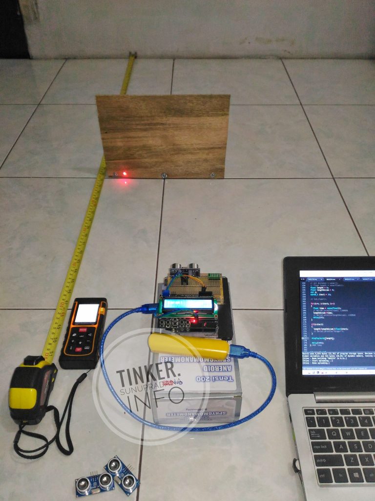 Gambar 24. Percobaan membandingkan hasil pengukuran alat-alat ukur dan cara pengukuran
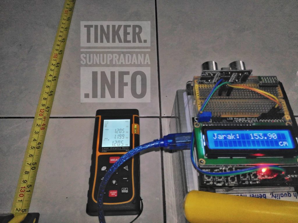 Gambar 25. Hasil pengukuran dengan pulseIn (float)
Pada Gambar 25 terlihat bahwa pengukuran jarak obyek dengan menggunakan pulseIn dan pembagian (float), tidak memberikan hasil yang mendekati dua alat ukur lainnya. Hasil dari pengukuran dari alat laser distance meter sama dengan penunjukkan pada tape rule. Jarak terukur 1.2 m (120.5 cm), sedangakan pembacaan sensor ultrasonik oleh program Arduino menunjukkan 153.90 cm.
Adadua kemungkinan, sumber kesalahan ada pada sensor atau ada pada Arduino. Pada sensor bisa jadi resolusi dan/atau akurasi, sedang pada Arduino bisa jadi ada pada hardware atau pada software. Pada software bisa jadi ada pada fungsi/pustaka dari perangkat lunak Arduino atau bisa jadi dari kode program oleh pengguna.
Pengujuan pertama dengan mengganti sensor (Gambar 24), hasilnya sama, nilai kesalahan masih pada kisaran yang sama. Percobaan berikutnya adalah dengan mengganti cara pembacaan dan pengolahan data dari sensor. Perhitungan dilakukan di dalam pustaka, pengguna mendapatkan hasil pengukuran dalam cm.
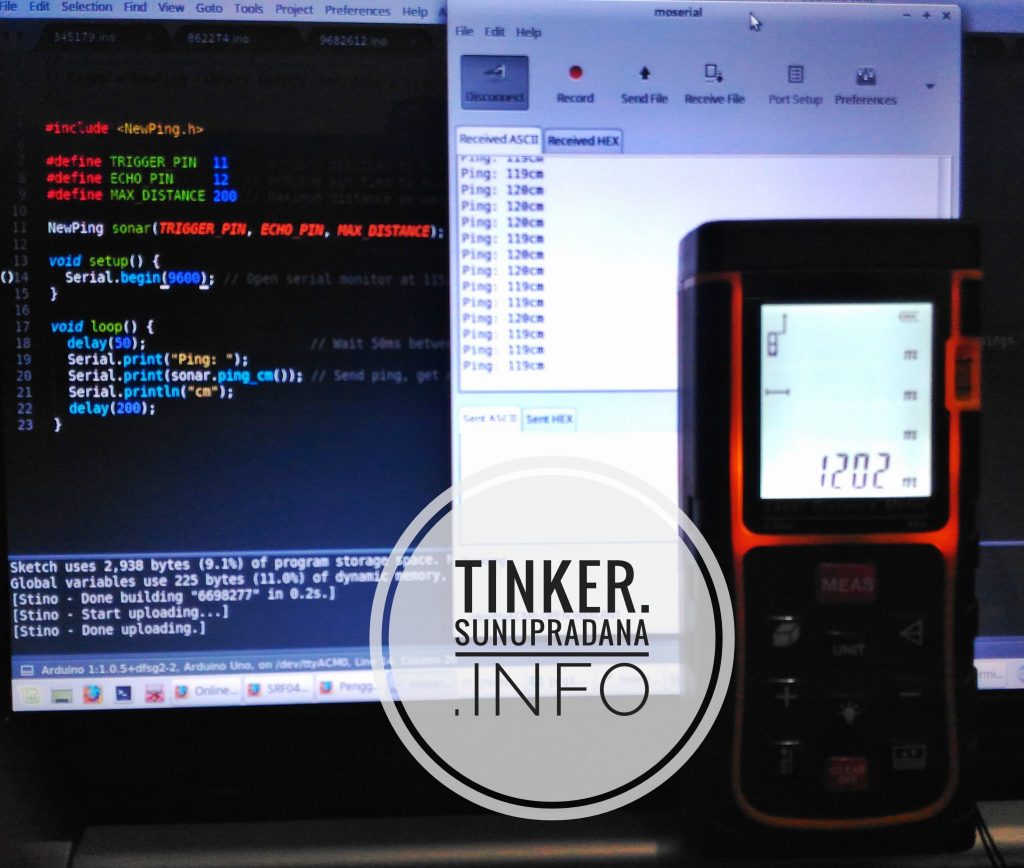 Gambar 26.
Dengan menggunakan library NewPing, akurasi hasil pengukuran bisa lebih dapat dicapai. Pengukuran dengan sensor ultrasonik menggunakan pustaka NewPing sama dengan hasil pengukuran dua alat lainnya pada setup percobaan yang sama.
Gambar 27. Percobaan pembandingan untuk jarak dekat
Kode percobaan perbandingan cara perhitungan.
/*************************************************************************************
  Menggunakan code template >>
  Mark Bramwell, July 2010
  This program will test the LCD panel and the buttons.When you push the button on the shield,
  the screen will show the corresponding one.
  Connection: Plug the LCD Keypad to the UNO(or other controllers)
  **************************************************************************************
  Kode dasar untuk NewPing oleh:Tim Eckel
  https://bitbucket.org/teckel12/arduino-new-ping/wiki/Home
  **************************************************************************************
  sunu pradana >> tinker.sunupradana.info
  **************************************************************************************/
#include <LiquidCrystal.h>
#include <Wire.h>
#include <NewPing.h>
LiquidCrystal lcd(8, 9, 4, 5, 6, 7);           // select the pins used on the LCD panel
#define btnRIGHT  0
#define btnUP     1
#define btnDOWN   2
#define btnLEFT   3
#define btnSELECT 4
#define btnNONE   5
#define TRIG_PIN  11
#define ECHO_PIN  12
#define MAX_DISTANCE 450 // Maximum distance we want to ping for (in centimeters). Maximum sensor distance is rated at 400-500cm.
const uint8_t BATAS_BAWAH = 5;
const uint16_t BATAS_ATAS = 250;
// define some values used by the panel and buttons
int lcd_key     = 0;
int adc_key_in  = 0;
int val = 2;
bool pertamaMode4;
int sonar(void);
int sonarFloat(void);
float displayJarak(void);
void calcByFloat(void);
void calcByInt58(void);
int bacaTombol(void);
NewPing sonarPING(TRIG_PIN, ECHO_PIN, MAX_DISTANCE); // NewPing setup of pins and maximum distance.
int read_LCD_buttons()
{
  adc_key_in = analogRead(0);       // read the value from the sensor
  // my buttons when read are centered at these valies: 0, 144, 329, 504, 741
  // we add approx 50 to those values and check to see if we are close
  // We make this the 1st option for speed reasons since it will be the most likely result
  if (adc_key_in > 1000) return btnNONE;
  // For V1.1 us this threshold
  if (adc_key_in < 50)   return btnRIGHT;
  if (adc_key_in < 250)  return btnUP;
  if (adc_key_in < 450)  return btnDOWN;
  if (adc_key_in < 650)  return btnLEFT;
  if (adc_key_in < 850)  return btnSELECT;
  // For V1.0 comment the other threshold and use the one below:
  /*
  if (adc_key_in < 50)   return btnRIGHT;
  if (adc_key_in < 195)  return btnUP;
  if (adc_key_in < 380)  return btnDOWN;
  if (adc_key_in < 555)  return btnLEFT;
  if (adc_key_in < 790)  return btnSELECT;
  */
  return btnNONE;                // when all others fail, return this.
}
void lcdTest001(void)
{
  lcd.begin(16, 2);
  lcd.setCursor(0,0);
  lcd.print("Uji sensor");
  lcd.setCursor(0,1);
  lcd.print("Ultrasonic");
}
void lcdShieldBtn(void)
{
  lcd.setCursor(9,1);
  lcd.print(millis()/1000);
  lcd.setCursor(0,1);
  lcd_key = read_LCD_buttons();
  switch (lcd_key)
  {               // depending on which button was pushed, we perform an action
    case btnRIGHT:
    {             //  push button "RIGHT" and show the word on the screen
      lcd.print("RIGHT ");
      break;
    }
    case btnLEFT:
    {
      lcd.print("LEFT   "); //  push button "LEFT" and show the word on the screen
      break;
    }
    case btnUP:
    {
      lcd.print("UP    ");  //  push button "UP" and show the word on the screen
      break;
    }
    case btnDOWN:
    {
      lcd.print("DOWN  ");  //  push button "DOWN" and show the word on the screen
      break;
    }
    case btnSELECT:
    {
      lcd.print("SELECT");  //  push button "SELECT" and show the word on the screen
      break;
    }
    case btnNONE:
    {
      lcd.print("NONE  ");  //  No action  will show "None" on the screen
      break;
    }//EOF btnNONE
  }//EOF switch
}//EOF lcdShieldBtn
void setup()
{
  Serial.begin(9600);
  lcd.begin(16, 2);               // start the library
  lcd.setCursor(0,0);             // set the LCD cursor   position
  lcdTest001();
  delay(1000);
  lcd.clear();
  pinMode(ECHO_PIN, INPUT);
  pinMode(TRIG_PIN, OUTPUT);
  delay(100);
}
void loop()
{
  // calcByFloat();
  // calcByInt58();
  // calcByNewPing();
  uint8_t tombol = bacaTombol();
  if(tombol !=0)
  {
    val = tombol;
    Serial.print("val: ");
    Serial.println(val);
    lcd.clear();
    lcd.setCursor(0,0);
    lcd.print("mode ukur: ");
    lcd.setCursor(12,0);
    lcd.print(val);
    delay(1000);
    lcd.noDisplay();
    delay(200);
    lcd.clear();
    lcd.display();
  }
  // Serial.println(pertamaMode4);
  switch ( val )
  {
    case 3:
    {
      calcByInt58();
      pertamaMode4 = true;
      break;
    }
    case 4:
    {
      if(pertamaMode4)
      {
        lcd.clear();
        lcd.setCursor(0,0);
        lcd.print("Mohon tunggu");
        delay(2000);
        lcd.noDisplay();
        // delay(200);
        lcd.clear();
        lcd.display();
        pertamaMode4 = false;
      }
      calcByFloat();
      // delay(10);
      break;
    }
    default:
    {
      calcByNewPing();
      pertamaMode4 = true;
      break;
    }
  }
  delay(10);
}//EOF loop
int sonar(void)
{
  digitalWrite(TRIG_PIN, HIGH);
  delayMicroseconds(12);
  digitalWrite(TRIG_PIN, LOW);
  int distanceSonar = pulseIn(ECHO_PIN, HIGH);
  return (distanceSonar = distanceSonar / 58);
}
int sonarFloat(void)
{
  digitalWrite(TRIG_PIN, HIGH);
  delayMicroseconds(12);
  digitalWrite(TRIG_PIN, LOW);
  int time = pulseIn(ECHO_PIN, HIGH);
  // float distance = (time / 29) / 2;
  // float distance = time / 58;
  // float distance = time * 0.034/2;
  // float distance = time * 0.035136/2;
  // float distanceFloat = time * 0.017568;
  return (time);
}
void displayJarak(float jarak)
{
  // Serial.print("Jarak dalam satuan cm:  ");
  lcd.setCursor(0,0);
  lcd.print("Jarak:");
  // Serial.println( sonar() );
  if(jarak<BATAS_BAWAH)
  {
    if(jarak = 0)
    {
      lcd.setCursor(8,0);
      lcd.print("               ");
      lcd.setCursor(5,1);
      lcd.print(" >>");
      lcd.setCursor(8,1);
      lcd.print(BATAS_ATAS);
      lcd.setCursor(14,1);
      lcd.print("cm");
      // delay(200);
      // lcd.clear();
    }
    else
    {
      // Serial.println("Obyek terlalu dekat");
      lcd.setCursor(8,0);
      lcd.print("               ");
      lcd.setCursor(0,1);
      lcd.print("               ");
      lcd.setCursor(5,1);
      lcd.print(" < ");
      lcd.setCursor(8,1);
      lcd.print(BATAS_BAWAH);
      lcd.setCursor(14,1);
      lcd.print("cm");
      // delay(200);
      // lcd.clear();
    }
  }
  else if(jarak>BATAS_ATAS)
  {
    // Serial.println("Terlalu jauh");
    lcd.setCursor(8,0);
    lcd.print("               ");
    lcd.setCursor(5,1);
    lcd.print(" > ");
    lcd.setCursor(8,1);
    lcd.print(BATAS_ATAS);
    lcd.setCursor(14,1);
    lcd.print("cm");
    // delay(200);
    // lcd.clear();
  }
  else
  {
    // Serial.println(jarak);
    lcd.setCursor(0,1);
    lcd.print("                ");
    lcd.setCursor(8,0);
    lcd.print(jarak);
    lcd.setCursor(14,1);
    lcd.print("cm");
  }
}
void calcByFloat(void)
{
  float length = 0;
  uint16_t timeAccum = 0;
  int i;
  uint8_t iter1 = 5;
  // lcd.clear();
  for(i=0; i<iter1; i++)
  {
    int time = sonarFloat();
    // Serial.println(time); //DEBUG
    timeAccum+=time;
    // Serial.println(timeAccum); //DEBUG
    delay(15);
    // Serial.println("Inner iter");
  }
  if(i=iter1)
  {
    // length=timeAccum/(float)iter1;
    int avgTime=timeAccum/iter1;
    // Serial.println("bingo!");
    // length = (avgTime / 29) / 2;
    // length = avgTime / 58;
    length = avgTime * 0.034/2;
    //  length = avgTime * 0.035136/2;
    // length = avgTime * 0.017568;
    // length = avgTime * 0.035/2;
  }
  // Serial.println("calcByFloat");
  displayJarak(length);
}
void calcByInt58(void)
{
  displayJarak( sonar() );
  delay(200);
}
void calcByNewPing(void)
{
  displayJarak( sonarPING.ping_cm() );
  delay(500);
}
int bacaTombol(void)
{
  adc_key_in = analogRead(0);       // read the value from the sensor
  if (adc_key_in > 1000) return 0;
  // For V1.1 us this threshold
  if (adc_key_in < 50)   return 5;
  if (adc_key_in < 250)  return 3;
  if (adc_key_in < 450)  return 4;
  if (adc_key_in < 650)  return 2;
  if (adc_key_in < 850)  return 1;
  return 0;                // when all others fail, return this.
}
- SRF04 - Ultra-Sonic Ranger Technical Specification
- SRF05 - Ultra-Sonic Ranger Technical Specification
- Arduino ultrasonic sensor (HC-SR04 or HY-SRF05)
- HC-SR05 / HY-SRF05 Precision Ultrasonic Sensor
- http://www.robot-electronics.co.uk/htm/sonar_faq.htm
- http://arduino-info.wikispaces.com/UltraSonicDistance
- Arduino–UltraSonic Sensor for Distance Measurement
- Tutorial: Ultrasonic Ranging with the Freedom Board
- Temperature compensation for an Arduino ultrasonic distance sensor
- Simulation of HC SR04 Ultrasonic range finder using Arduino