PIR (Passive infRared) sensor, adalah sensor yang mengukur radiasi infra merah dari suatu obyek. Seperti yang terlihat dari namanya, PIR diketahui bekerja secara pasif, artinya hanya menerima radiasi saja dan tidak memancarkan radiasi. PIR memberikan sinyal saat ada perubahan dari tingkat radiasi infra merah, karenanya PIR dipakai sebagai sensor gerakan. Keterangan lebih jauh bisa dipelajari dari beberapa kutipan berikut:
Gambar 3. [sumber]Gambar 4. [sumber]Gambar 5. [sumber]
 Gambar 6. [sumber]
Specifications:
- Operating voltage range: DC 4.5-20V
- Quiescent Current: <50uA
- Level output: High 3.3 V /Low 0V
- Trigger: L can not be repeated trigger/H can be repeated trigger (Default repeated trigger)
- Delay time: 5-200S(adjustable) the range is (0.xx second to tens of second)
- Block time: 1S(default) Can be made a range(0.xx to tens of seconds
- Board Dimensions: 32mm*24mm
- Angle Sensor: <100 ° cone angle
- Operation Temp: -15℃-+70℃
- Lens size sensor: Diameter:23mm(Default)
Features:
- the automatic sensor: to enter the sensor output range is high, people leave the sensor range of the automatic delay off high, output low.
- the photosensitive control (optional, factory is not set) may set the photosensitive control during the day or light intensity without induction.
- the temperature compensation (optional, factory is not set): In the summer when the ambient temperature rises to 30 ~ 32 ℃, slightly shorter detection range, temperature compensation can be used as a performance compensation.
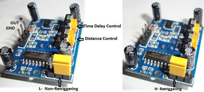
- two trigger mode: (can be selected by jumpers) a, can not repeat the trigger: the sensor output high, the delay time is over, the output will automatically become low from high; b, repeatable trigger: the sensor output high after the delay period, if the human body in its sensing range activities, its output will remain high until after the delay will be left high to low (sensor module review Measured activities of each body will be automatically extended after a delay time, and the final event of the delay time Starting point of time).
- with induction blocking time (the default setting: 2.5S block time): sensor module, after each sensor output (high change Into a low level),you can set up a blockade followed by time period, in this time period the sensor does not accept any sensor signal. This feature can have a “sensor output time” and “blocking time” the interval between the work produced can be applied to detect the interval Products; also inhibit this function during load switching for a variety of interference. (This time can be set at zero seconds - Tens of seconds).
- the working voltage range: the default voltage DC4.5V-20V.
- micro-power consumption: static current “50 microamps, especially for battery-powered automatic control products.
- the output high level signals: types of circuits can be easily and docking.
- the working voltage range: the default voltage DC4.5V-20V.
- the working voltage range: the default voltage DC4.5V-20V.
Instructions:
- Sensing module for about a minute after power initialization time, during the interval to the output module 0-3 times a minute in standby mode.
- Should avoid direct lighting such as interference sources close the surface of the lens module so as to avoid the introduction of interference signal generator malfunction; use of the environment to avoid the flow of the wind, the wind sensor will also cause interference.<50uA
- Sensor module using a dual probe, the probe’s window is rectangular, dual (A per B million) in the direction of the ends of long, when the body passed from left to right or right to left when the reach the dual IR time, distance difference, the greater the difference, more sensitive sensors, when the body from the front to the probe or from top to bottom or from bottom to top direction passing, dual IR not detected changes in the distance, no difference value, the sensor insensitive or does not work; so the sensors should be installed dual direction of the probe with human activities as much as possible parallel to the direction of maximum to ensure that the body has been passed by the dual sensor probe. To increase the sensing range of angles, the module using a circular lens, the probe also makes sense on all four sides, but still higher than the upper and lower left and right direction of sensing range, sensitivity and strong, still as far as possible by the above installation requirements.VCC, trig (control side), echo (receiving end), GND
Note:
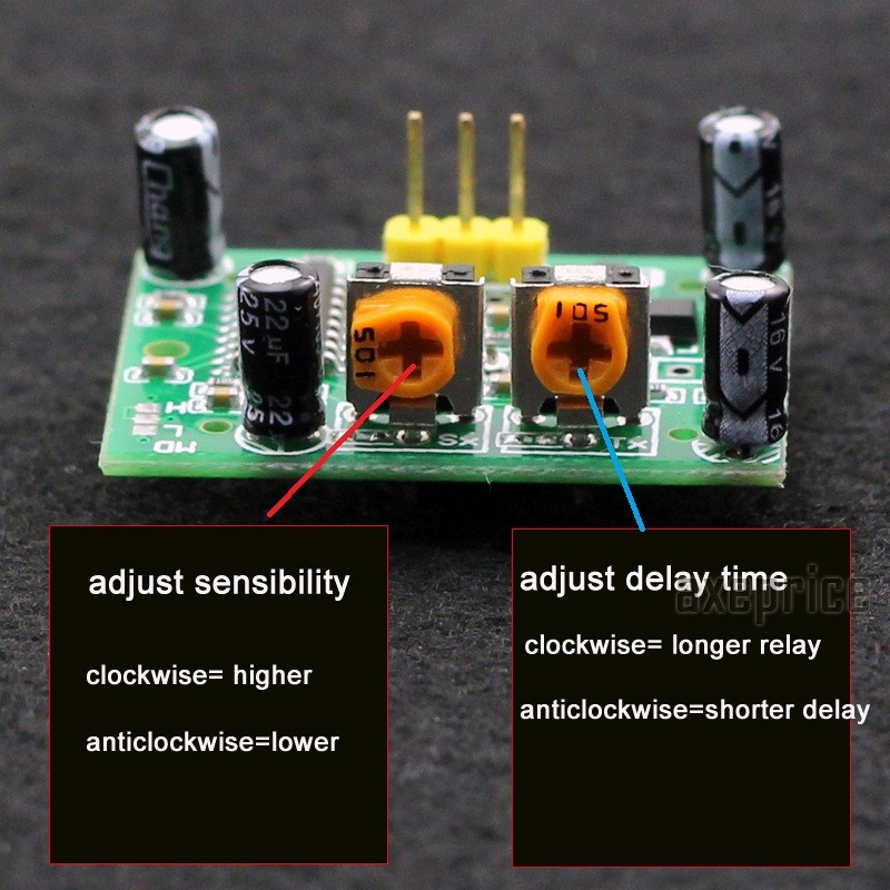
- The potentiometer clockwise to adjust the distance, sensing range increases (about 7 meters), on the contrary, sensing range decreases (about 3 meters).Delay adjustment potentiometer clockwise rotation, sensor delay longer (about 300S), the other hand, induction by the short delay (about 5S).
- In the beginning you might notice some seemingly erratic behavior – this is perfectly normal. We need to understand a few things before we can tweak the settings.
- When connecting the battery, the sensor will take up to 30 to 60 seconds to stabilize (warm up).
- Place your setup in such a way that there will be no motion and wait until the LED remains OFF.
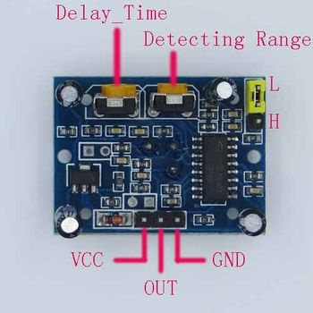
DELAY TIME
SENSITIVITY ADJUST/DETECTING RANGE
 Gambar 9. [sumber]
RETRIGER/RETRIGGERING
 [Gambar 10.]
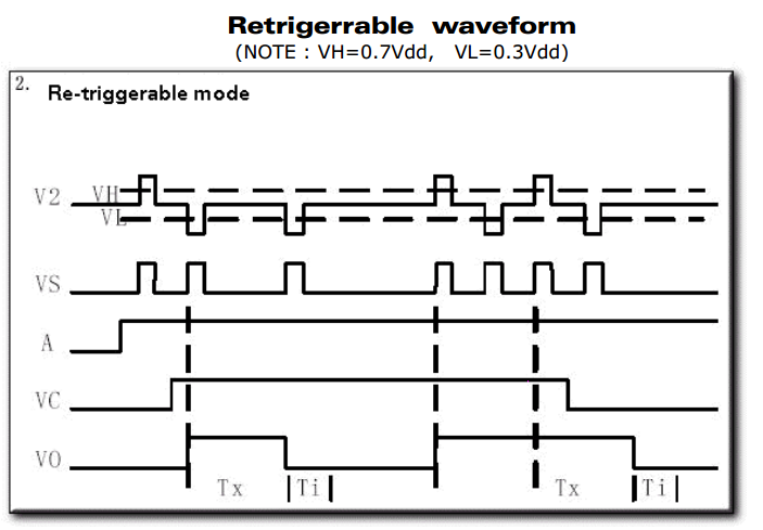
Gambar 10. [sumber]
 Gambar 11. [sumber]
Untuk pengujian alat, proses belajar awal dan bahkan untuk tuning, konfigurasi seperti pada Gambar 10 dan Gambar 11 adalah yang paling memudahkan. Tidak ada delay tambahan dari program dan proses lain pada mikrokontroler. Pengguna dapat lebih mudah untuk memperhatikan dan mempelajari respon modul PIR. Pengaturan delay time dan sensitivity menjadi lebih mudah dilakukan dengan cara ini.
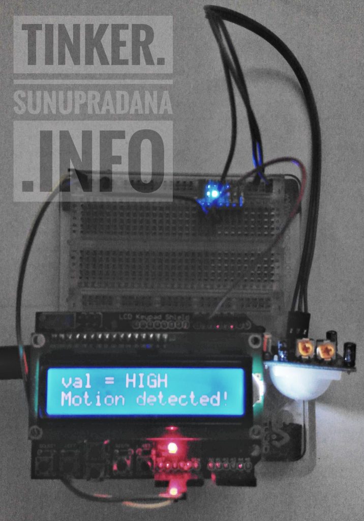 Gambar 12.
Contoh pengujuan seperti pada Gambar 12, menggunakan dua indikator bantuan. LED memudahkan kita untuk mengetahui tingkat tegangan sebagai penunjuk langsung kondisi deteksi modul. Kondisi LED yang menyala atau tidak menyala membantu proses analisis program untuk mikrokontroler (dalam hal ini sistem papan Arduino). Seberapa cepat respon program yang kita buat bila dibandingkan dengan kondisi deteksi modul PIR.
Setelah proses pengaturan awal menggunakan cara pada Gambar 10 dan Gambar 11, pemrograman pada Gambar 12 menggunakan kode berikut. Tentu dapat dan perlu dilakukan coba-coba, proses trial & error, tinkering untuk hasil yang sesuai seperti yang dikehendaki.
/*************************************************************************************
  Mark Bramwell, July 2010
  This program will test the LCD panel and the buttons.When you push the button on the shield,
  the screen will show the corresponding one.
  Connection: Plug the LCD Keypad to the UNO(or other controllers)
  **************************************************************************************/
#include <LiquidCrystal.h>
#include <Wire.h>
LiquidCrystal lcd(8, 9, 4, 5, 6, 7);           // select the pins used on the LCD panel
#define btnRIGHT  0
#define btnUP     1
#define btnDOWN   2
#define btnLEFT   3
#define btnSELECT 4
#define btnNONE   5
const uint8_t INPUT_PIR = 12;
// define some values used by the panel and buttons
int lcd_key     = 0;
int adc_key_in  = 0;
int val = 0;
uint8_t pirState = LOW;
int read_LCD_buttons()
{               // read the buttons
  adc_key_in = analogRead(0);       // read the value from the sensor
  // my buttons when read are centered at these valies: 0, 144, 329, 504, 741
  // we add approx 50 to those values and check to see if we are close
  // We make this the 1st option for speed reasons since it will be the most likely result
  if (adc_key_in > 1000) return btnNONE;
  // For V1.1 us this threshold
  if (adc_key_in < 50)   return btnRIGHT;
  if (adc_key_in < 250)  return btnUP;
  if (adc_key_in < 450)  return btnDOWN;
  if (adc_key_in < 650)  return btnLEFT;
  if (adc_key_in < 850)  return btnSELECT;
  // For V1.0 comment the other threshold and use the one below:
  /*
  if (adc_key_in < 50)   return btnRIGHT;
  if (adc_key_in < 195)  return btnUP;
  if (adc_key_in < 380)  return btnDOWN;
  if (adc_key_in < 555)  return btnLEFT;
  if (adc_key_in < 790)  return btnSELECT;
  */
  return btnNONE;                // when all others fail, return this.
}
void lcdTest001(void)
{
  lcd.begin(16, 2);               // start the library
  lcd.setCursor(0,0);             // set the LCD cursor   position
  lcd.print("Uji PIR >>");  // print a simple message on the LCD
}
void lcdShieldTest001(void)
{
  lcd.setCursor(9,1);             // move cursor to second line "1" and 9 spaces over
  lcd.print(millis()/1000);       // display seconds elapsed since power-up
  lcd.setCursor(0,1);             // move to the begining of the second line
  lcd_key = read_LCD_buttons();   // read the buttons
  switch (lcd_key)
  {               // depending on which button was pushed, we perform an action
    case btnRIGHT:
    {             //  push button "RIGHT" and show the word on the screen
      lcd.print("RIGHT ");
      break;
    }
    case btnLEFT:
    {
      lcd.print("LEFT   "); //  push button "LEFT" and show the word on the screen
      break;
    }
    case btnUP:
    {
      lcd.print("UP    ");  //  push button "UP" and show the word on the screen
      break;
    }
    case btnDOWN:
    {
      lcd.print("DOWN  ");  //  push button "DOWN" and show the word on the screen
      break;
    }
    case btnSELECT:
    {
      lcd.print("SELECT");  //  push button "SELECT" and show the word on the screen
      break;
    }
    case btnNONE:
    {
      lcd.print("NONE  ");  //  No action  will show "None" on the screen
      break;
    }//EOF btnNONE
  }//EOF switch
}//EOF lcdShieldTest001
void pirinit(void)
{
  pinMode(INPUT_PIR, INPUT);     // declare sensor as input
}
/*
  Fungsi adapirtest disalin dari:
  https://learn.adafruit.com/pir-passive-infrared-proximity-motion-sensor?view=all
*/
void adapirtest(void)
{
  val = digitalRead(INPUT_PIR);  // read input value
  if (val == HIGH) // check if the input is HIGH
  {
    lcd.clear();
    // digitalWrite(ledPin, HIGH);  // turn LED ON
    lcd.setCursor(0,0);
    lcd.print("val = HIGH");
    if (pirState == LOW)
    {
      // we have just turned on
      // Serial.println("Motion detected!");
      lcd.setCursor(0,1);
      lcd.print("Motion detected!");
      delay(3000);
      // We only want to print on the output change, not state
      pirState = HIGH;
    }
    delay(1000);
  }
  else
  {
    lcd.clear();
    // digitalWrite(ledPin, LOW); // turn LED OFF
    lcd.setCursor(0,0);
    lcd.print("val = LOW");
    if (pirState == HIGH)
    {
      // we have just turned of
      // Serial.println("Motion ended!");
      lcd.setCursor(0,1);
      lcd.print("Motion ended!");
      delay(3000);
      // We only want to print on the output change, not state
      pirState = LOW;
    }
    delay(1000);
  }
}
void setup()
{
  // Serial.begin(9600);
  lcd.begin(16, 2);               // start the library
  lcd.setCursor(0,0);             // set the LCD cursor   position
  lcdTest001();
  delay(1000);
  lcd.clear();
  pirinit();
}
void loop()
{
  // lcdShieldTest001();
  adapirtest();
  // delay(1000);
}
[/su_panel]
[su_panel border=”3px solid #FFD104″ radius=”10″]
[/su_panel]
[su_panel border=”3px solid #990066″ radius=”10″]
[/su_panel]