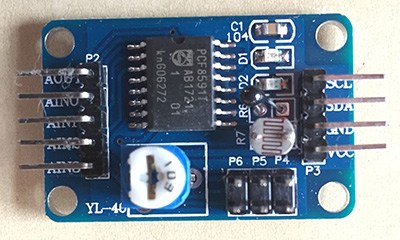
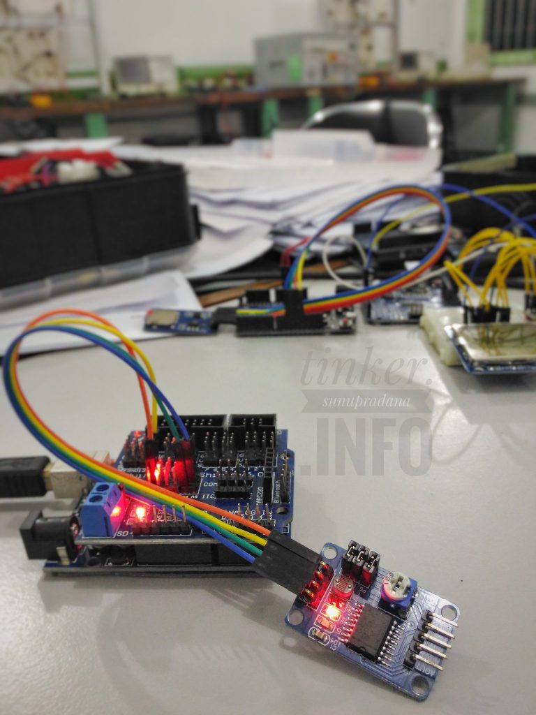
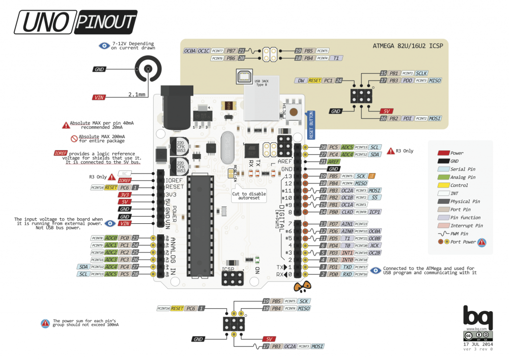
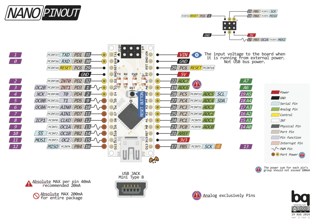
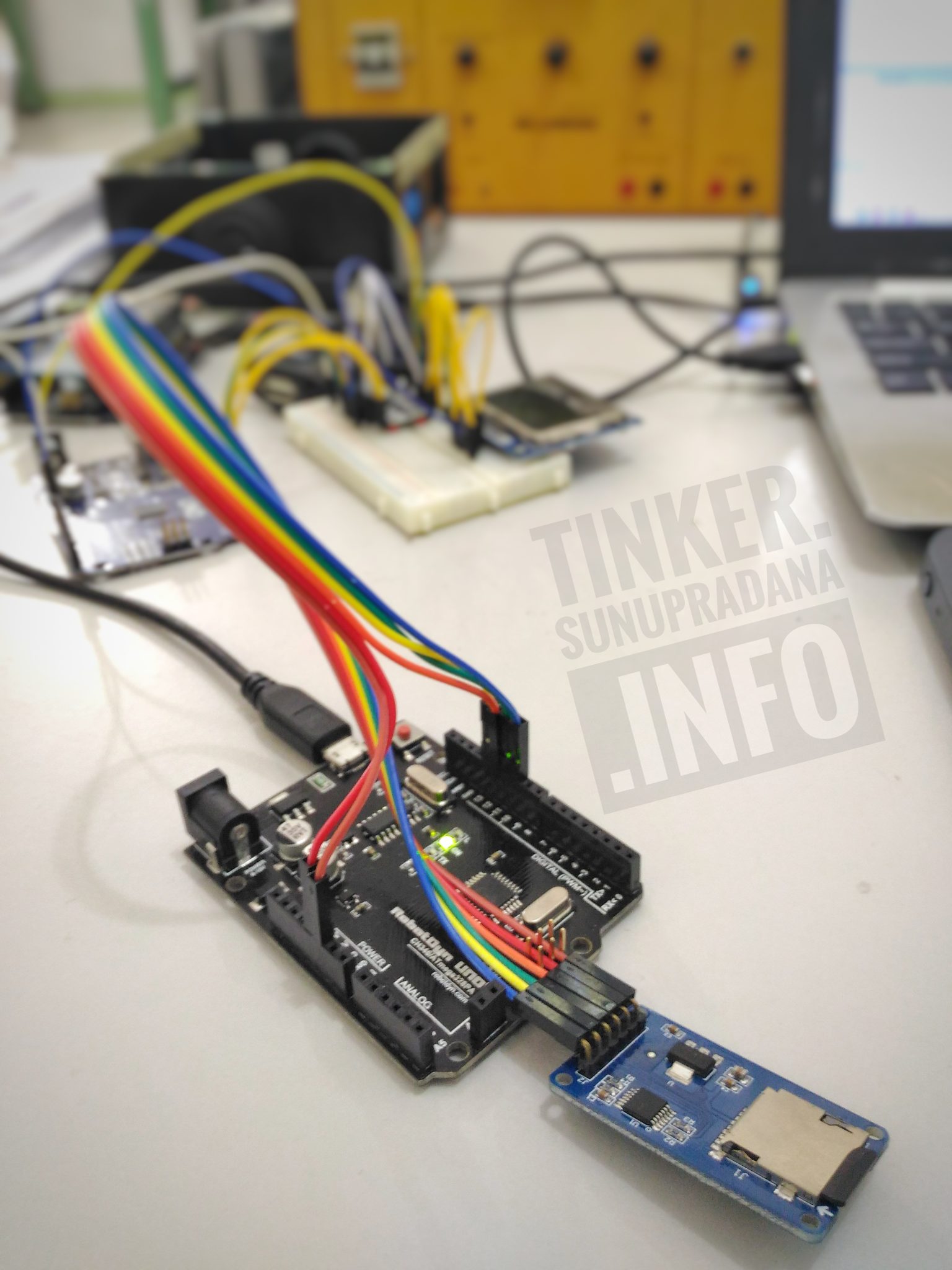
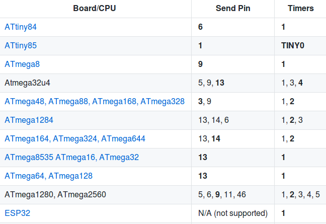
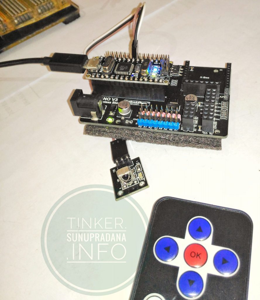
PCF8591: 8-bit A/D and D/A converter { ADC }

[ [ images & links ] ]
[su_panel border=”3px solid #482DE3″ radius=”10″]

Gambar 1.

PCF8591Gambar 2. [einhugur.com]

Features

  • Module supports external voltage input of the 4-way acquisition (voltage input range of 0-5v)
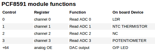
  • integrated photoresistor
  • integrated thermistor
  • integrated potentiometer
  • Modules power indicator
  • Modules with DA output indicator, when the module DA output interface voltage reaches a certain value, will be lit panel the DA output indicator, the higher the voltage, the more obvious indicator brightness
  • Remove shunts to bypass on board integrated devices

 The left connector

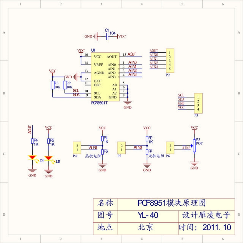
  • AOUT chip DA output interface
  • AINO chip analog input interface 0
  • AIN1 chip analog input interface 1
  • AIN2 chip analog input interface 2
  • AIN3 chip analog input interface 3

  The right connector

  • SCL
  • SDA
  • GND
  • VCC – connected to  3.3v-5v

Gambar 3. [arduinolearning.com]


Gambar 4. [arduinolearning.com]
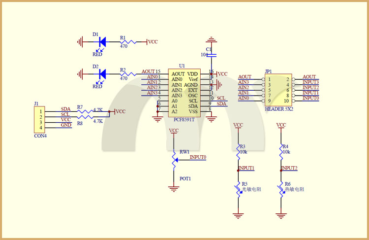
 

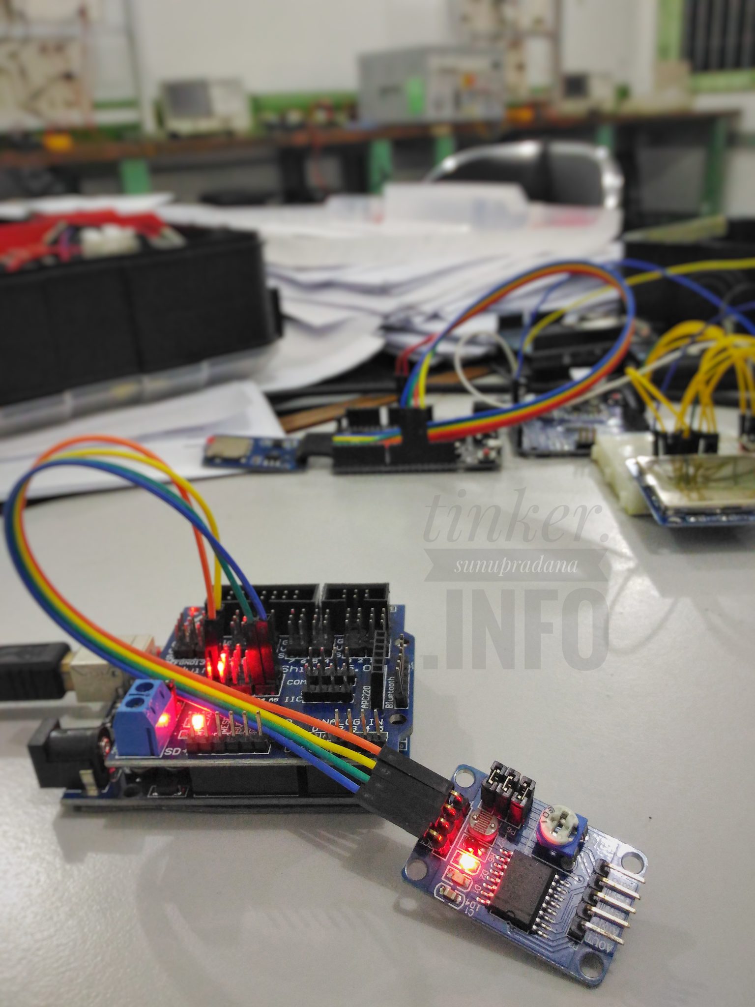
Gambar 5.[forum.arduino.cc]


Product Description [electrodragon.com]

[/su_panel] [su_panel border=”3px solid #E1E555″ radius=”10″] [/su_panel] [su_panel border=”3px solid #C0FFC0″ radius=”10″]

Gambar 6.

Gambar 7.

[/su_panel] [su_panel border=”3px solid #8E2DEF” radius=”10″] [/su_panel]


Micro SD adapter

[ [ images & links ] ]
[su_panel border=”3px solid #482DE3″ radius=”10″]

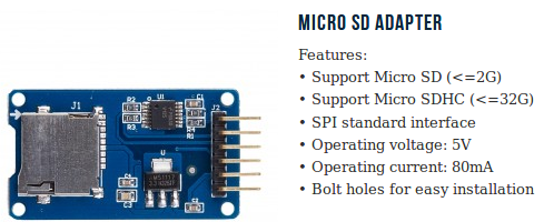
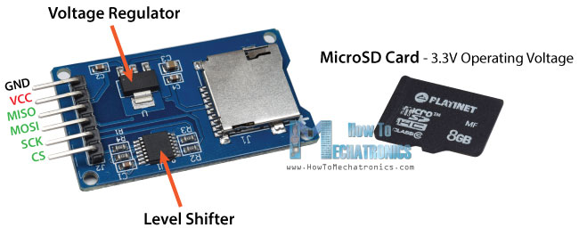
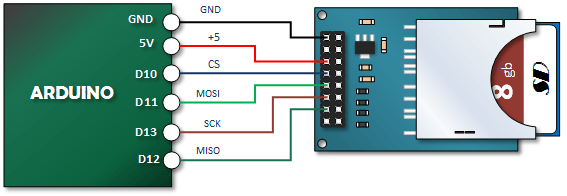
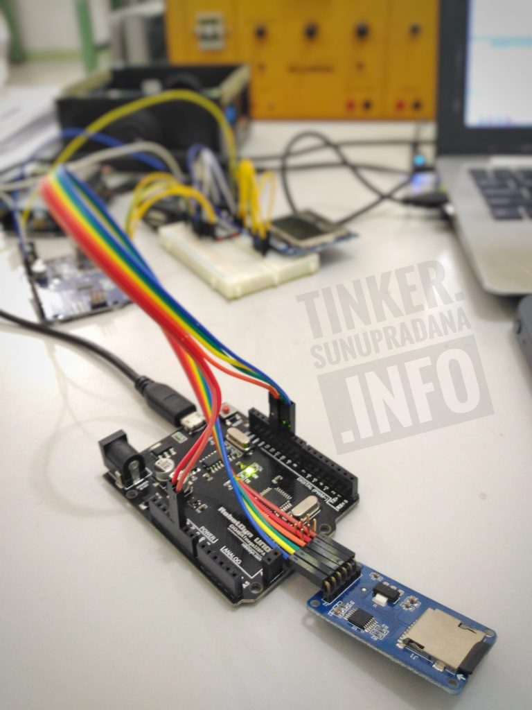
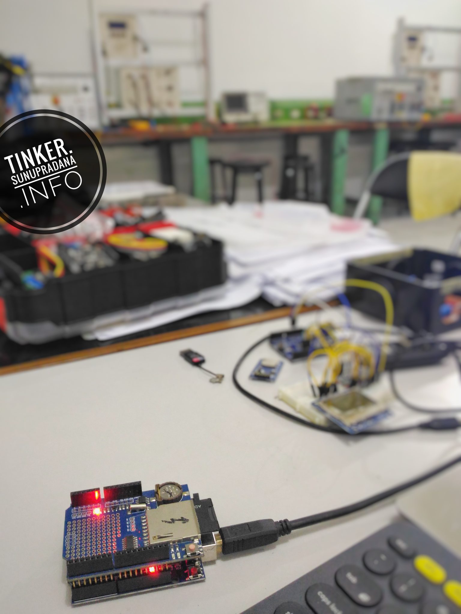
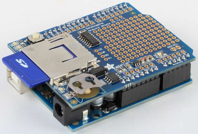
Pada mashup sebelumnya, telah diungkapkan mengenai data logging shield. Di papan logger yang ditujukan untuk ukuran papan Arduino Uno itu sudah terdapat RTC. Namun ukuran sistem itu relatif besar dan karenanya pin papan itu tidak mudah diterapkan di sistem lain seperti papan Arduino Nano atau papan Arduino Micro. Alternatif lain adalah MicroSD Card Adapter seperti yang akan ditampilkan di halaman ini.

Gambar 1. [elabpeers.com]

[/su_panel] [su_panel border=”3px solid #30C0F0″ radius=”10″] [/su_panel] [su_panel border=”3px solid #FF6666″ radius=”10″]

Arduino SD Card and Data Logging to Excel Tutorial :

Gambar 3.


Arduino Data Logging

Now let’s make another more interesting example of data logging a temperature sensor. For that purpose we will use the DS3231 Real Time Clock module which has a built-in temperature sensor as well. You can find more details about how to connect and use this module in my previous tutorial.

So after connecting the two modules to the Arduino let’s take a look at the code for this example.

[/su_panel] [su_panel border=”3px solid #6C9C29″ radius=”10″]

Arduino LC Studio SD Card Tutorial :


Gambar 4. [henrysbench.capnfatz.com]

[/su_panel] [su_panel border=”3px solid #990066″ radius=”10″]

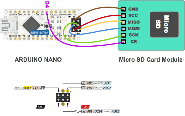
Arduino Nano SD Card Connection :

Arduino Nano SD Card ConnectionGambar 5.


[/su_panel] [su_panel border=”3px solid #30C0F0″ radius=”10″]

What is a Data-logger [datalogger.pbworks.com ]

[/su_panel] [su_panel border=”3px solid #30C0F0″ radius=”10″]

Gambar 6.

[/su_panel] [su_panel border=”3px solid #39DECB” radius=”10″] [intense_tabs direction=”right” active_tab_background_color=”#000000″ active_tab_font_color=”#ffff00″ trigger=”click”] [intense_tab title=”Video01″ border=”3px solid #e8e8e8″ link_target=”_self” content_background_color=”#000000″ content_font_color=”#ffffff” icon_size=”1″ icon_position=”left”]

[/intense_tab] [intense_tab title=”Video02″ border=”3px solid #e8e8e8″ link_target=”_self” icon_size=”1″ content_background_color=”#000000″ content_font_color=”#ffffff” icon_position=”left”]

[/intense_tab] [intense_tab title=”Video03″ border=”3px solid #e8e8e8″ link_target=”_self” icon_size=”1″ content_background_color=”#000000″ content_font_color=”#ffffff” icon_position=”left”]

[/intense_tab] [intense_tab title=”Video04″ border=”3px solid #e8e8e8″ link_target=”_self” icon_size=”1″ content_background_color=”#000000″ content_font_color=”#ffffff” icon_position=”left”]

[/intense_tab] [intense_tab title=”Video05″ border=”3px solid #e8e8e8″ link_target=”_self” icon_size=”1″ content_background_color=”#000000″ content_font_color=”#ffffff” icon_position=”left”]

[/intense_tab] [intense_tab title=”Video06″ border=”3px solid #e8e8e8″ link_target=”_self” icon_size=”1″ content_background_color=”#000000″ content_font_color=”#ffffff” icon_position=”left”]

[/intense_tab] [/intense_tabs] [/su_panel] [su_panel border=”3px solid #202DB9″ radius=”10″] [/su_panel]

Data logging shield

[ [ images & links ] ]
[su_panel border=”3px solid #482DE3″ radius=”10″]

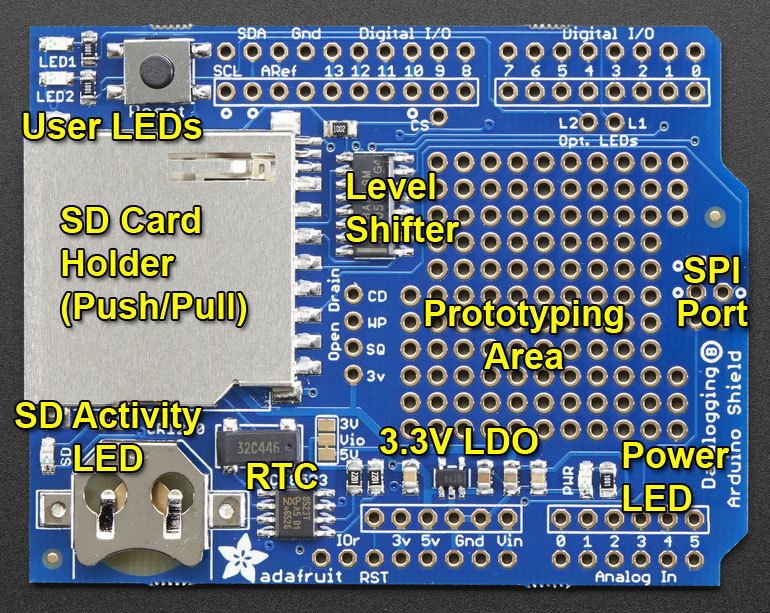
https://learn.adafruit.com/adafruit-data-logger-shield?view=all :

Gambar 1. learn.adafruit.com


adafruit_products_labeled.jpgGambar 2.

Place the SD library folder your sketchbook libraries folder. You may need to create the libraries subfolder if its your first library.


[/su_panel] [su_panel border=”3px solid #30C0F0″ radius=”10″]

https://learn.adafruit.com/adafruit-data-logger-shield?view=all :

adafruit_products_Logger_bb.jpgGambar 3.

[/su_panel] [su_panel border=”3px solid #FF6666″ radius=”10″]

Adafruit library examples.

Deek-Robot: Data logging shield V1.0

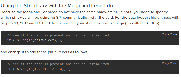
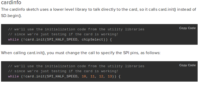
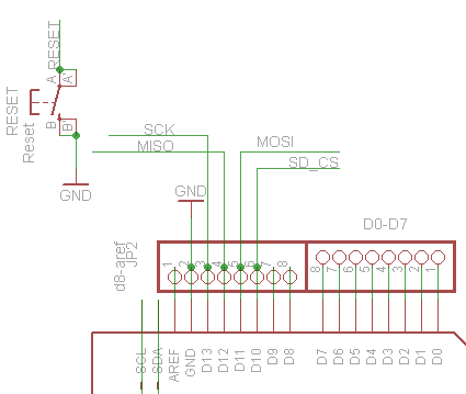
D10 – Chip Select
D11 – SPI MOSI
D12 – SPI MISO
D13 – SPI SCK

[/su_panel] [su_panel border=”3px solid #6C9C29″ radius=”10″] [/su_panel] [su_panel border=”3px solid #990066″ radius=”10″] [/su_panel] [su_panel border=”3px solid #30C0F0″ radius=”10″]
[code lang=”C”] RTC_DS1307 RTC; // define the Real Time Clock object

// for the data logging shield, we use digital pin 10 for the SD cs line
const int chipSelect = 10;

// the logging file
File logfile;

void error(char *str)
{
Serial.print("error: ");
Serial.println(str);

// red LED indicates error
digitalWrite(redLEDpin, HIGH);

while(1);
}
[/code]

“Next is the error() function, which is just a shortcut for us, we use it when something Really Bad happened, like we couldn’t write to the SD card or open it. It prints out the error to the Serial Monitor, turns on the red error LED, and then sits in a while(1); loop forever, also known as a halt

[code lang=”C”] // initialize the SD card
Serial.print("Initializing SD card…");
// make sure that the default chip select pin is set to
// output, even if you don’t use it:
pinMode(10, OUTPUT);

// see if the card is present and can be initialized:
if (!SD.begin(chipSelect)) {
Serial.println("Card failed, or not present");
// don’t do anything more:
return;
}
Serial.println("card initialized.");

// create a new file
char filename[] = "LOGGER00.CSV";
for (uint8_t i = 0; i < 100; i++) {
filename[6] = i/10 + ‘0’;
filename[7] = i%10 + ‘0’;
if (! SD.exists(filename)) {
// only open a new file if it doesn’t exist
logfile = SD.open(filename, FILE_WRITE);
break; // leave the loop!
}
}

if (! logfile) {
error("couldnt create file");
}

Serial.print("Logging to: ");
Serial.println(filename);
[/code]

“Now the code starts to talk to the SD card, it tries to initialize the card and find a FAT16/FAT32 partition. Next it will try to make a logfile. We do a little tricky thing here, we basically want the files to be called something like LOGGERnn.csv where nn is a number. By starting out trying to create LOGGER00.CSV and incrementing every time when the file already exists, until we get to LOGGER99.csv, we basically make a new file every time the Arduino starts up To create a file, we use some Unix style command flags which you can see in the logfile.open() procedure. FILE_WRITE means to create the file and write data to it. Assuming we managed to create a file successfully, we print out the name to the Serial port.”

[code lang=”C”] Wire.begin();
if (!RTC.begin()) {
logfile.println("RTC failed");
#if ECHO_TO_SERIAL
Serial.println("RTC failed");
#endif //ECHO_TO_SERIAL
}

logfile.println("millis,time,light,temp");
#if ECHO_TO_SERIAL
Serial.println("millis,time,light,temp");
#if ECHO_TO_SERIAL// attempt to write out the header to the file
if (logfile.writeError || !logfile.sync()) {
error("write header");
}

pinMode(redLEDpin, OUTPUT);
pinMode(greenLEDpin, OUTPUT);

// If you want to set the aref to something other than 5v
//analogReference(EXTERNAL);
}
[/code]

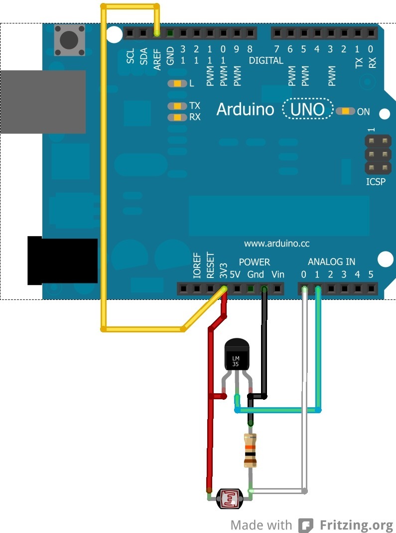
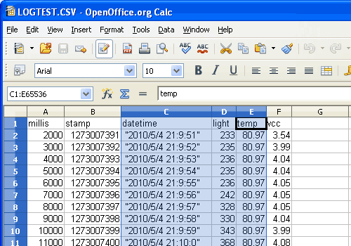
“OK we’re wrapping up here. Now we kick off the RTC by initializing the Wire library and poking the RTC to see if its alive. Then we print the header. The header is the first line of the file and helps your spreadsheet or math program identify whats coming up next. The data is in CSV (comma separated value) format so the header is too: “millis,time,light,temp” the first item millis is milliseconds since the Arduino started, time is the time and date from the RTC, light is the data from the CdS cell and temp is the temperature read. You’ll notice that right after each call to logfile.print() we have #if ECHO_TO_SERIAL and a matching Serial.print() call followed by a #if ECHO_TO_SERIAL this is that debugging output we mentioned earlier. The logfile.print() call is what writes data to our file on the SD card, it works pretty much the same as the Serial version. If you set ECHO_TO_SERIAL to be 0 up top, you won’t see the written data printed to the Serial terminal. Finally, we set the two LED pins to be outputs so we can use them to communicate with the user. There is a commented-out line where we set the analog reference voltage. This code assumes that you will be using the ‘default’ reference which is the VCC voltage for the chip – on a classic Arduino this is 5.0V. You can get better precision sometimes by lowering the reference. However we’re going to keep this simple for now! Later on, you may want to experiment with it.”

Main loop

Now we’re onto the loop, the loop basically does the following over and over:

  • Wait until its time for the next reading (say once a second – depends on what we defined)
  • Ask for the current time and date froom the RTC
  • Log the time and date to the SD card
  • Read the photocell and temperature sensor
  • Log those readings to the SD card
  • Sync data to the card if its time
[code lang=”C”] void loop(void)
{
DateTime now;

// delay for the amount of time we want between readings
delay((LOG_INTERVAL -1) – (millis() % LOG_INTERVAL));

digitalWrite(greenLEDpin, HIGH);

// log milliseconds since starting
uint32_t m = millis();
logfile.print(m); // milliseconds since start
logfile.print(", ");
#if ECHO_TO_SERIAL
Serial.print(m); // milliseconds since start
Serial.print(", ");
#endif

// fetch the time
now = RTC.now();
// log time
logfile.print(now.get()); // seconds since 2000
logfile.print(", ");
logfile.print(now.year(), DEC);
logfile.print("/");
logfile.print(now.month(), DEC);
logfile.print("/");
logfile.print(now.day(), DEC);
logfile.print(" ");
logfile.print(now.hour(), DEC);
logfile.print(":");
logfile.print(now.minute(), DEC);
logfile.print(":");
logfile.print(now.second(), DEC);
#if ECHO_TO_SERIAL
Serial.print(now.get()); // seconds since 2000
Serial.print(", ");
Serial.print(now.year(), DEC);
Serial.print("/");
Serial.print(now.month(), DEC);
Serial.print("/");
Serial.print(now.day(), DEC);
Serial.print(" ");
Serial.print(now.hour(), DEC);
Serial.print(":");
Serial.print(now.minute(), DEC);
Serial.print(":");
Serial.print(now.second(), DEC);
#endif //ECHO_TO_SERIAL
[/code]

  “The first important thing is the delay() call, this is what makes the Arduino wait around until its time to take another reading. If you recall we #defined the delay between readings to be 1000 millseconds (1 second). By having more delay between readings we can use less power and not fill the card as fast. Its basically a tradeoff how often you want to read data but for basic long term logging, taking data every second or so will result in plenty of data! Then we turn the green LED on, this is useful to tell us that yes we’re reading/writing data now. Next we call millis() to get the ‘time since arduino turned on’ and log that to the card. It can be handy to have – especially if you end up not using the RTC. Then the familiar RTC.now() call to get a snapshot of the time. Once we have that, we write a timestamp (seconods since 2000) as well as the date in YY/MM/DD HH:MM:SS time format which can easily be recognized by a spreadsheet. We have both because the nice thing about a timestamp is that its going to montonically increase and the nice thing about printed out date is its human readable.”

[/su_panel] [su_panel border=”3px solid #FF6666″ radius=”10″] https://learn.adafruit.com/adafruit-data-logger-shield?view=all :

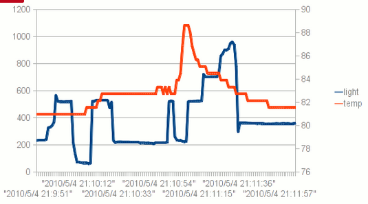
Plotting with a spreadsheet


adafruit_products_dataselect.gifGambar 4.


Gambar 5.

[/su_panel] [su_panel border=”3px solid #00C700″ radius=”10″] https://learn.adafruit.com/adafruit-data-logger-shield?view=all :

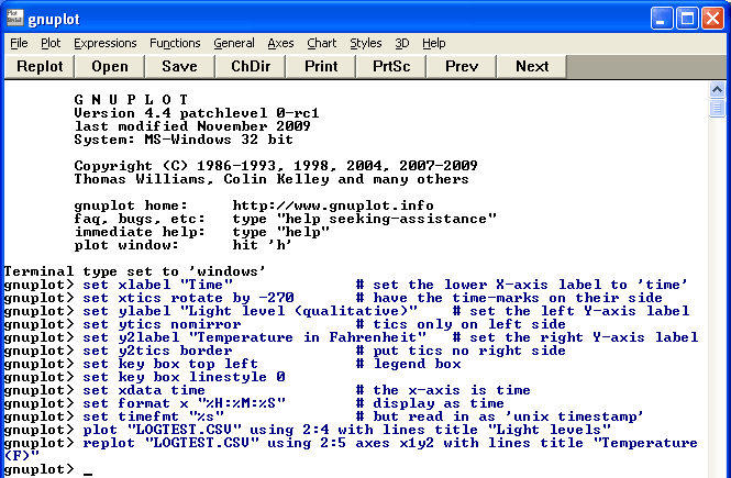
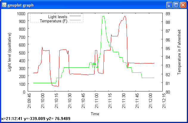
Using Gnuplot

set xlabel "Time"              # set the lower X-axis label to 'time'

set xtics rotate by -270       # have the time-marks on their side


set ylabel "Light level (qualitative)"    # set the left Y-axis label

set ytics nomirror             # tics only on left side

set y2label "Temperature in Fahrenheit"   # set the right Y-axis label
set y2tics border              # put tics no right side

set key box top left           # legend box
set key box linestyle 0 

set xdata time                 # the x-axis is time
set format x "%H:%M:%S"        # display as time
set timefmt "%s"               # but read in as 'unix timestamp'

plot "LOGTEST.CSV" using 2:4 with lines title "Light levels" 
replot "LOGTEST.CSV" using 2:5 axes x1y2 with lines title "Temperature (F)"

adafruit_products_gnuplotcmd.gifGambar 6.

adafruit_products_gnuplotted.gifGambar 7.

[/su_panel] [su_panel border=”3px solid #990066″ radius=”10″]

https://learn.adafruit.com/adafruit-data-logger-shield?view=all :

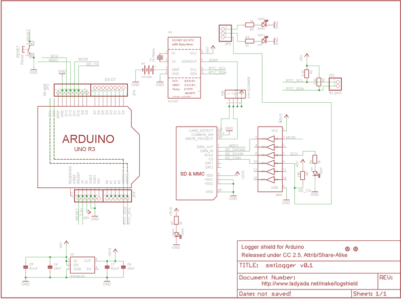
adafruit_products_adafruitlogshieldsch.pngGambar 8.

Gambar 9.

Gambar 10.

Gambar 11.

Gambar 12.

[/su_panel]


Save

Save

Save

Save

LCD Nokia 5110 + sistem Arduino

[ [ images, codes & links ] ]
[su_panel border=”3px solid #482DE3″ radius=”10″]

The Nokia 5110 display has long been an Arduino Hobbyist favorite and a search of the internet will show that there are tons of different ways to drive this device.

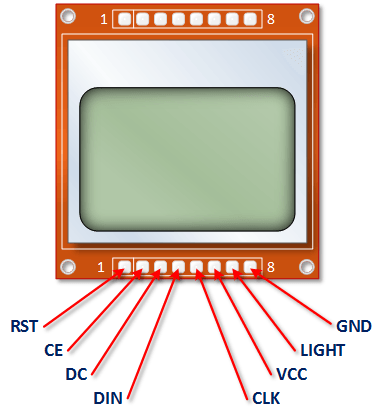
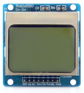
There are a few varieties of this module are out there.   Mine are labeled as you see below.   Others should work just fine with this tutorial if you map your pins correctly.

Remember,  VCC is 3.3 Volts.   The LIGHT Control can use pulse width modulation through a 330 ohm resistor.

https://sunupradana.info/tkr/wp-content/uploads/2017/07/Nokia-5110-Pinouts.png

Gambar 1.


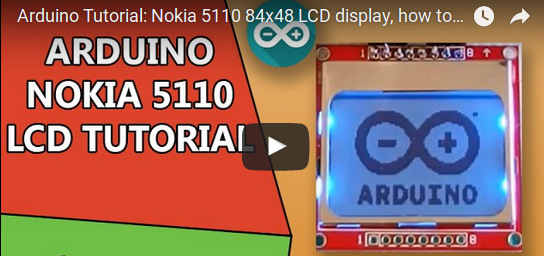
~Arduino Nokia 5110 with U8GLIB Tutorial


LCD Specifications

  • Controller: PCD8544
  • Supply: 2.7V to 3.3V
  • Interface levels: 2.7V to 5V
  • Backlight Colour: Blue
  • Backlight supply: 3.3V Max
  • Module size: W 43.6mm x H 43.1mm
  • Working current: < 200uA (Backlight off)

Notice that the module only needs 3.3v from the Arduino. More information can be found on the Datasheet located here.

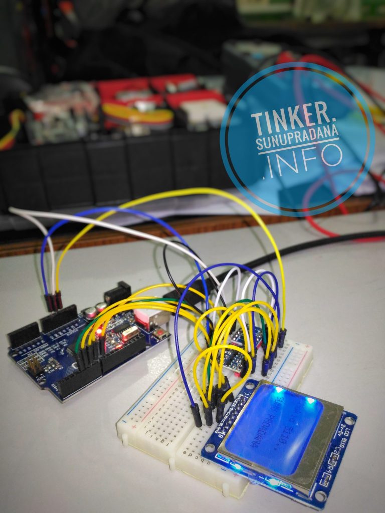
nokiaGambar 2. [sumber]

lcdGambar 3. [sumber]

~hackshed.co.uk

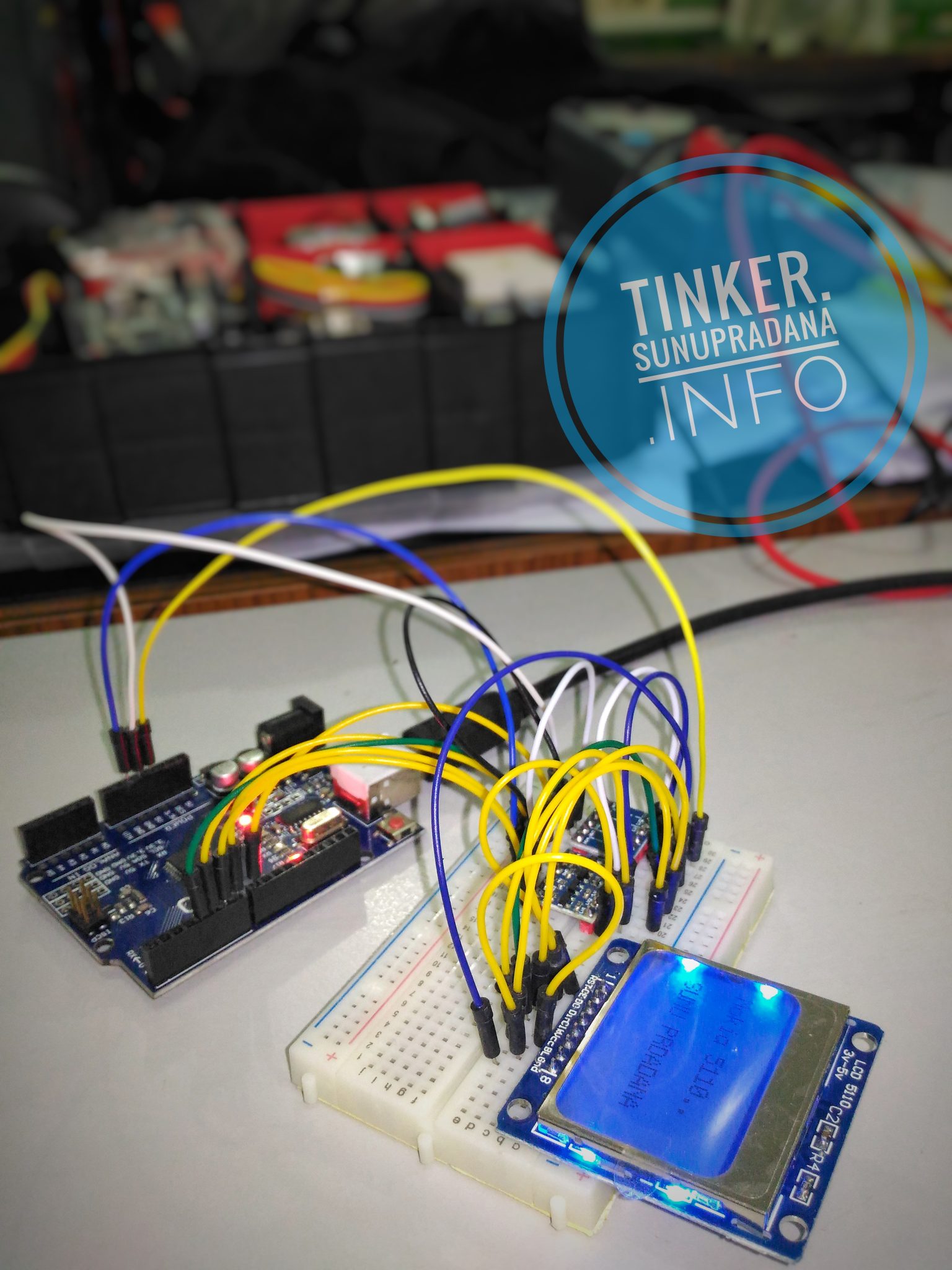
Koneksi pada Gambar 3 hanya contoh, pin pada Arduino dapat diatur sesuai keperluan dan dukungan pustaka.

[/su_panel] [su_panel border=”3px solid #30C0F0″ radius=”10″]

Gambar 4.


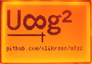
Untuk penggunaan LCD Nokia 5110, salah satu pustaka yang bisa dipergunakan adalah u8glib (atau versi yang lebih baru u8g2). Sebagai contoh untuk uji coba, dapat diikuti kode program dari: henrysbench.capnfatz.com berikut:

// Henry's Bench
// Arduino Nokia 5110 U8Glib Tutorial


#include "U8glib.h"


#define backlight 11
 
//Delcare the display and assign the pins
 
//U8GLIB_PCD8544 u8g(8, 4, 7, 5, 6);  // CLK=8, DIN=4, CE=7, DC=5, RST=6
 
 
U8GLIB_PCD8544 u8g(8, 4, 7, 5, 6);  // CLK=8, DIN=4, CE=7, DC=5, RST=6

 
void draw() {
 
  u8g.setFont(u8g_font_profont11);  // select font
  u8g.drawStr(0, 15, "Nokia 5110..");  // put string of display at position X, Y
  u8g.drawStr(29, 35, "HELLO!!!!");
  
  
}
 
void setup() 
{
  // Set Backlight Intensity
  // 0 is Fully bright
  // 255 is off
  analogWrite(backlight, 20);
  //
  // Enter the U8Glib Picture Loop
  //
  
}
 
void loop() 
{ 
 u8g.firstPage(); 
  do 
  {
    draw();
  } while( u8g.nextPage() ); 
  
}
[/su_panel] [su_panel border=”3px solid #FF6666″ radius=”10″]

Salah satu pustaka/library yang umum dipergunakan untuk LCD Nokia 5110 adalah pustaka  yang dikeluarkan oleh Adafruit. Terdapat dua bagian pustaka untuk lcd ini, satu adalah untuk driver hardware dan satu untuk pustaka grafik.

Urutan pin LCD 5110 pada produk Adafruit bisa jadi tidak sama dengan urutan pin LCD 5110 yang bisa dibeli di pasaran lokal (impor dari China). Meskipun begitu, pustaka dapat dipergunakan dan berfungsi secara normal.


Testing

You can find our Nokia Display Arduino library on github. To install it, click this button to download the compressed ZIP file then install it. This guide will help you with the install process if you have never installed an Arduino library.

Then you’ll have to do the same for the Adafruit GFX Graphics core library, available from github. Click the button to download it. Then install Adafruit_GFX just like the library you’ve done except this time name it Adafruit_GFX, etc.

Restart the Arduino software. You should see a new example folder called Adafruit_PCD8544 and inside, an example called pcdtest. Open up that sketch and upload it to your Arduino. You should see the example test sequence.

Graphics Library

We have a ready to go basic graphics library that has primitives for bitmaps, shapes and text. You can probably do everything you want using it. Because of the way the display works we need to buffer the entire display in ram which is 84×48 bits (504 bytes). However, screen updates are very fast.

For more details about the Adafruit GFX library, please visit http://learn.adafruit.com/adafruit-gfx-graphics-library – it supports lines, rectangles, roundrects, circles, text of different sizes etc.

Note that since this display is MONOCHROMATIC it only supports two colors: BLACK or WHITE. BLACK is a displayed dot and WHITE is for erasing pixels

Dont forget, after drawing anything to the screen, call display() to write it out to the LCD!

Downloads

Our PCD8544 (Nokia 5110) LCD display Arduino library is on github which comes with example code. This library uses 1/2 Kbytes of RAM since it needs to buffer the entire display but its very fast! The code is simple to adapt to any other microcontroller.

You’ll also need to get the Adafruit GFX Graphics core library which can print text, bitmaps, pixels, rectangles, circles and lines, also available on github.

The PCD8544 datasheet tells you all about what the display can do.

~learn.adafruit.com


[/su_panel] [su_panel border=”3px solid #6C9C29″ radius=”10″]

https://raw.githubusercontent.com/wiki/olikraus/u8g2/img/uc1701_dogs102_uno_board_320.jpgGambar 5. [u8g2/wiki]

[/su_panel] [su_panel border=”3px solid #990066″ radius=”10″]
[/su_panel] [su_panel border=”3px solid #FF6666″ radius=”10″]

Library: LCD5110_Basic

[/su_panel] [su_panel border=”3px solid #D572FF” radius=”10″]

Library: LCD5110_Graph


[/su_panel] [su_panel border=”3px solid #30C0F0″ radius=”10″]

Videos >>
[/su_panel] [su_panel border=”3px solid #CE228C” radius=”10″]

[/su_panel]


Save

Save

Save

Save

Save

Save

Save

Save

Save

Save

Save

Save

Save

Belajar penggunaan LCD “Nokia 5110” di sistem Arduino [video]

[ [ videos ] ]
[su_panel border=”3px solid #30C0F0″ radius=”10″] [intense_tabs direction=”right” active_tab_background_color=”#000000″ active_tab_font_color=”#ffff00″ trigger=”click”] [intense_tab title=”Video01″ border=”3px solid #e8e8e8″ link_target=”_self” content_background_color=”#000000″ content_font_color=”#ffffff” icon_size=”1″ icon_position=”left”]

[/intense_tab] [intense_tab title=”Video02″ border=”3px solid #e8e8e8″ link_target=”_self” icon_size=”1″ content_background_color=”#000000″ content_font_color=”#ffffff” icon_position=”left”]

[/intense_tab] [intense_tab title=”Video03″ border=”3px solid #e8e8e8″ link_target=”_self” icon_size=”1″ content_background_color=”#000000″ content_font_color=”#ffffff” icon_position=”left”]

[/intense_tab] [intense_tab title=”Video04″ border=”3px solid #e8e8e8″ link_target=”_self” icon_size=”1″ content_background_color=”#000000″ content_font_color=”#ffffff” icon_position=”left”]

[/intense_tab] [intense_tab title=”Video05″ border=”3px solid #e8e8e8″ link_target=”_self” icon_size=”1″ content_background_color=”#000000″ content_font_color=”#ffffff” icon_position=”left”]

[/intense_tab] [intense_tab title=”Video06″ border=”3px solid #e8e8e8″ link_target=”_self” icon_size=”1″ content_background_color=”#000000″ content_font_color=”#ffffff” icon_position=”left”]

[/intense_tab] [/intense_tabs] [/su_panel] [su_panel border=”3px solid #FF6666″ radius=”10″] [intense_tabs direction=”right” active_tab_background_color=”#000000″ active_tab_font_color=”#ffff00″ trigger=”click”] [intense_tab title=”Video07″ border=”3px solid #e8e8e8″ link_target=”_self” content_background_color=”#000000″ content_font_color=”#ffffff” icon_size=”1″ icon_position=”left”]

[/intense_tab] [intense_tab title=”Video08″ border=”3px solid #e8e8e8″ link_target=”_self” icon_size=”1″ content_background_color=”#000000″ content_font_color=”#ffffff” icon_position=”left”]

[/intense_tab] [intense_tab title=”Video09″ border=”3px solid #e8e8e8″ link_target=”_self” icon_size=”1″ content_background_color=”#000000″ content_font_color=”#ffffff” icon_position=”left”]

[/intense_tab] [intense_tab title=”Video10″ border=”3px solid #e8e8e8″ link_target=”_self” icon_size=”1″ content_background_color=”#000000″ content_font_color=”#ffffff” icon_position=”left”]

[/intense_tab] [intense_tab title=”Video11″ border=”3px solid #e8e8e8″ link_target=”_self” icon_size=”1″ content_background_color=”#000000″ content_font_color=”#ffffff” icon_position=”left”]

[/intense_tab] [intense_tab title=”Video12″ border=”3px solid #e8e8e8″ link_target=”_self” icon_size=”1″ content_background_color=”#000000″ content_font_color=”#ffffff” icon_position=”left”]

[/intense_tab] [/intense_tabs] [/su_panel] [su_panel border=”3px solid #00C700″ radius=”10″] [intense_tabs direction=”right” active_tab_background_color=”#000000″ active_tab_font_color=”#ffff00″ trigger=”click”] [intense_tab title=”Video13″ border=”3px solid #e8e8e8″ link_target=”_self” content_background_color=”#000000″ content_font_color=”#ffffff” icon_size=”1″ icon_position=”left”]

[/intense_tab] [intense_tab title=”Video14″ border=”3px solid #e8e8e8″ link_target=”_self” icon_size=”1″ content_background_color=”#000000″ content_font_color=”#ffffff” icon_position=”left”]

[/intense_tab] [intense_tab title=”Video15″ border=”3px solid #e8e8e8″ link_target=”_self” icon_size=”1″ content_background_color=”#000000″ content_font_color=”#ffffff” icon_position=”left”]

[/intense_tab] [/intense_tabs] [/su_panel]


Logic level converter

[ [ images & links ] ]
[su_panel border=”3px solid #228BAE” radius=”10″]

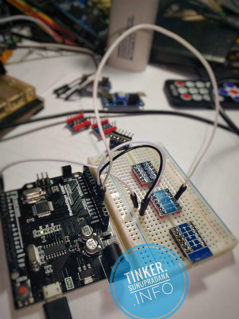
Papan logic level converter sering diperlukan jika bekerja dengan dua atau lebih sistem yang mempergunakan tingkat tegangan yang berbeda. Sistem yang bekerja di tingkat tegangan 3.3 V dan tidak memiliki toleransi tegangan sampai 5 V akan sangat mungkin mengalami kerusakan. Untuk mencegahnya diperlukan sistem yang mengalihkan level logika digital dari sistem 5 V dari dan ke level 3.3 V.

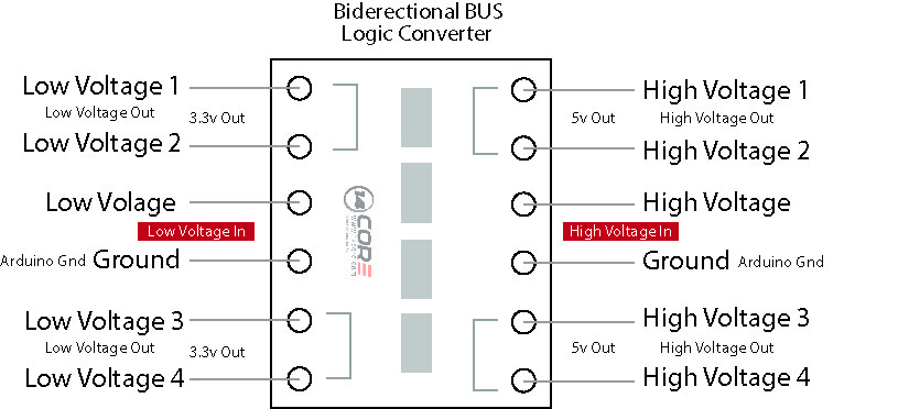
Penggunaan sistemnya cukup sederhana, yang penting untuk diingat adalah bahwa sumber tegangan di kedua sisi perlu dihubungkan. Jika misalnya sisi 3.3 V tidak memiliki catau daya sendiri maka pergunakan sumber lain dengan tegangan yang sama sebesar 3.3 V. Contohnya dari papan Arduino, hubungkan 5 V dan 3.3 V ke pin masing-masing yang sesuai. Adapun pin Gnd sudah terhubung antar sisi, sehingga level yang dikonversi diukur berdasarkan acuan yang sama. Jadi, Gnd untuk sistem (termasuk untuk ground sisi 3.3 V) bisa didapatkan hanya dari satu hubungan ke GND pada papan Arduino.


Do you have a 3.3V I2C or SPI sensor that might go up in smoke if connected to a 5V Arduino? Or a 5V device that needs a workaround to be compatible with your 3.3V Raspberry Pi, Arduino Due or pcDuino?

To get over this obstacle you need a device that can shift 3.3V up to 5V or 5V down to 3.3V. This is called logic level shifting. Level shifting is a dilemma so common we designed a simple PCB assembly to make interfacing devices a little easier: the Bi-Directional Logic Level Converter.

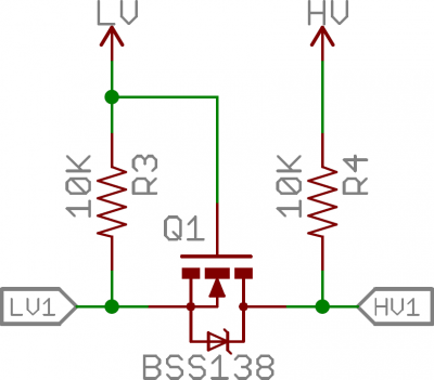
MOSFET logic level shifting circuitGambar 1.

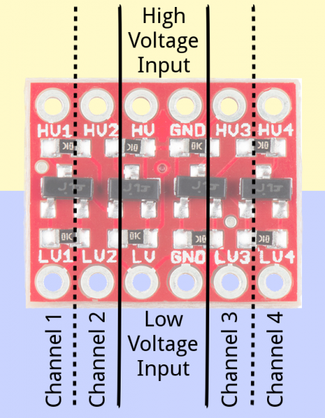
Annotated BD-LLCGambar 2.


~learn.sparkfun.com


I2c-Bi-Directional-021Gambar 3. [14core.com]


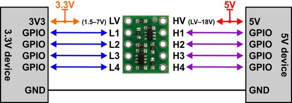
As digital devices get smaller and faster, once ubiquitous 5 V logic has given way to ever lower-voltage standards like 3.3 V, 2.5 V, and even 1.8 V, leading to an ecosystem of components that need a little help talking to each other. For example, a 5 V part might fail to read a 3.3 V signal as high, and a 3.3 V part might be damaged by a 5 V signal. This level shifter solves these problems by offering bidirectional voltage translation of up to four independent signals, converting between logic levels as low as 1.5 V on the lower-voltage side and as high as 18 V on the higher-voltage side, and its compact size and breadboard-compatible pin spacing make it easy to integrate into projects.

Gambar 4.

This logic level converter requires two supply voltages: the lower-voltage logic supply (1.5 V to 7 V) connects to the LV pin and the higher-voltage supply (LV to 18 V) connects to the HV pin. The HV supply must be higher than the LV supply for proper operation. Logic low voltages will pass directly from Hx to the corresponding Lx (and vice versa), while logic high voltages will be converted between the HV level to the LV level as the signal passes from Hx to Lx or Lx to Hx.

~www.pololu.com/product/2595

[/su_panel] [su_panel border=”3px solid #00C700″ radius=”10″]

Gambar 5.

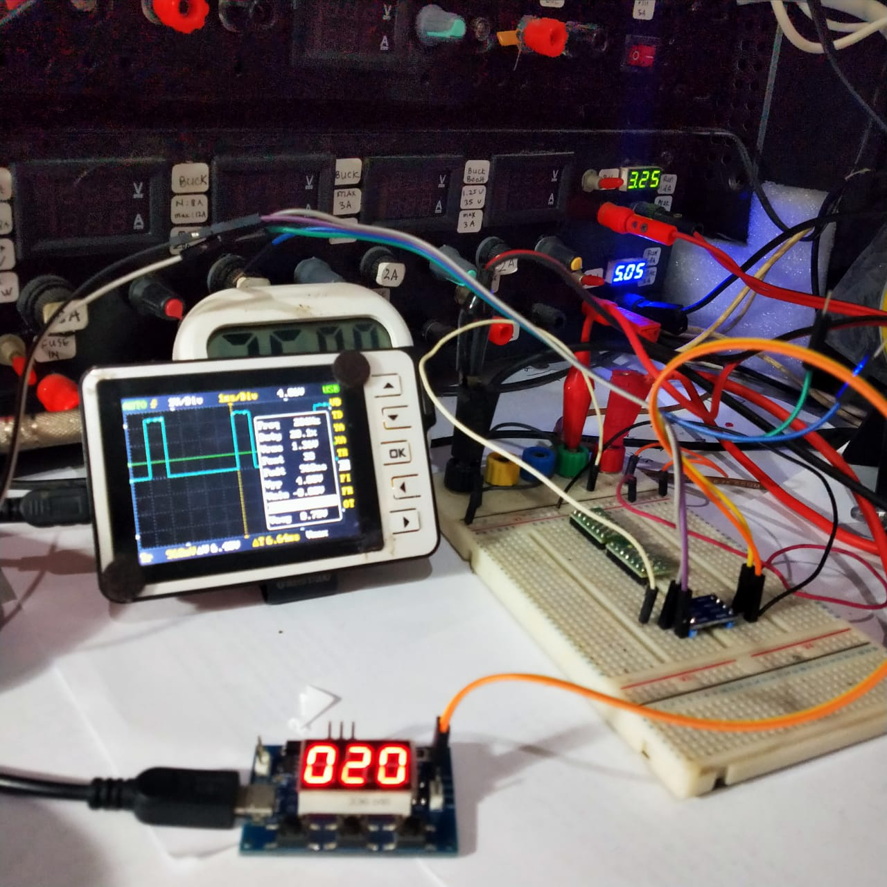
Sebagai awalan pengujian sebaiknya dilakukan hanya dengan tegangan DC yang relatif stabil (rata) di input terlebih dahulu. Ukur level tegangan input dan level tegangan output. Apakah nilai tegangan 5 V sudah benar turun (dikonversi) menjadi 3.3 V? Apakah, sebaliknya juga, level tegangan bisa naik dari 3.3 V ke 5 V? Berikutnya baru lakukan percobaan dengan penyakelaran gelombang kotak, karena bentuk gelombang ini adalah bentuk gelombang digital yang paling umum dipergunakaan. Mulailah dari frekuensi rendah dengan pulsa high yang cukup lebar, lalu persempit lebar pulsa high. Teruskan dengan menaikkan frekuensi dan ulangi prosedur mempersempit pulsa high seperti langkah sebelumnya. Demikian seterusnya sampai anda lihat batas lebar pulsa dan/atau batas frekuensi di mana logic converter tidak lagi berfungsi dengan baik.

Gambar 6.

Di Gambar 6, saya mencoba mengggunakan pembangkit gelombang kotak PWM yang sudah sangat banyak dijual bebas di pasaran. Frekuensi yang dipakai diatur sebesar 200 Hz (terukur 201 Hz) dan seperti terlihat di Gambar 6, duty cycle diatur sebesar 20%. Tegangan keluaran modul ini sekitar sebesar 5 V peak.


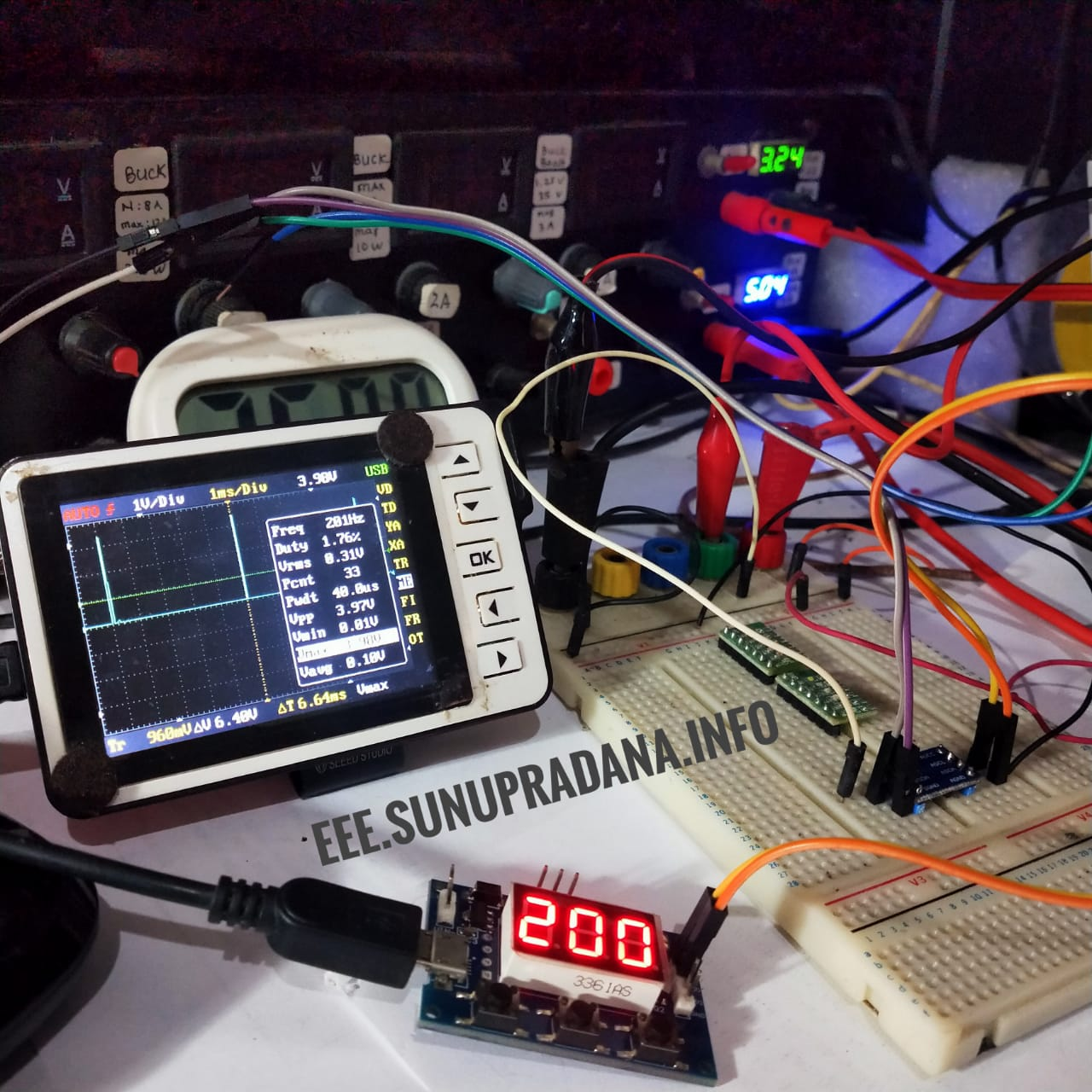
Gambar 7.

Di Gambar 7 terlihat percobaan pengukuran di sisi tegangan logic level yang lebih rendah. Frekuensi penyakelaran tetap 200 Hz, tetapi lebar pulsa hanya sebesar 40 μS. Tegangan Vpp yang terukur masih sekitar 3.97 V, level tegangan yang jelas masih lebih tinggi dari 3.3 V. 


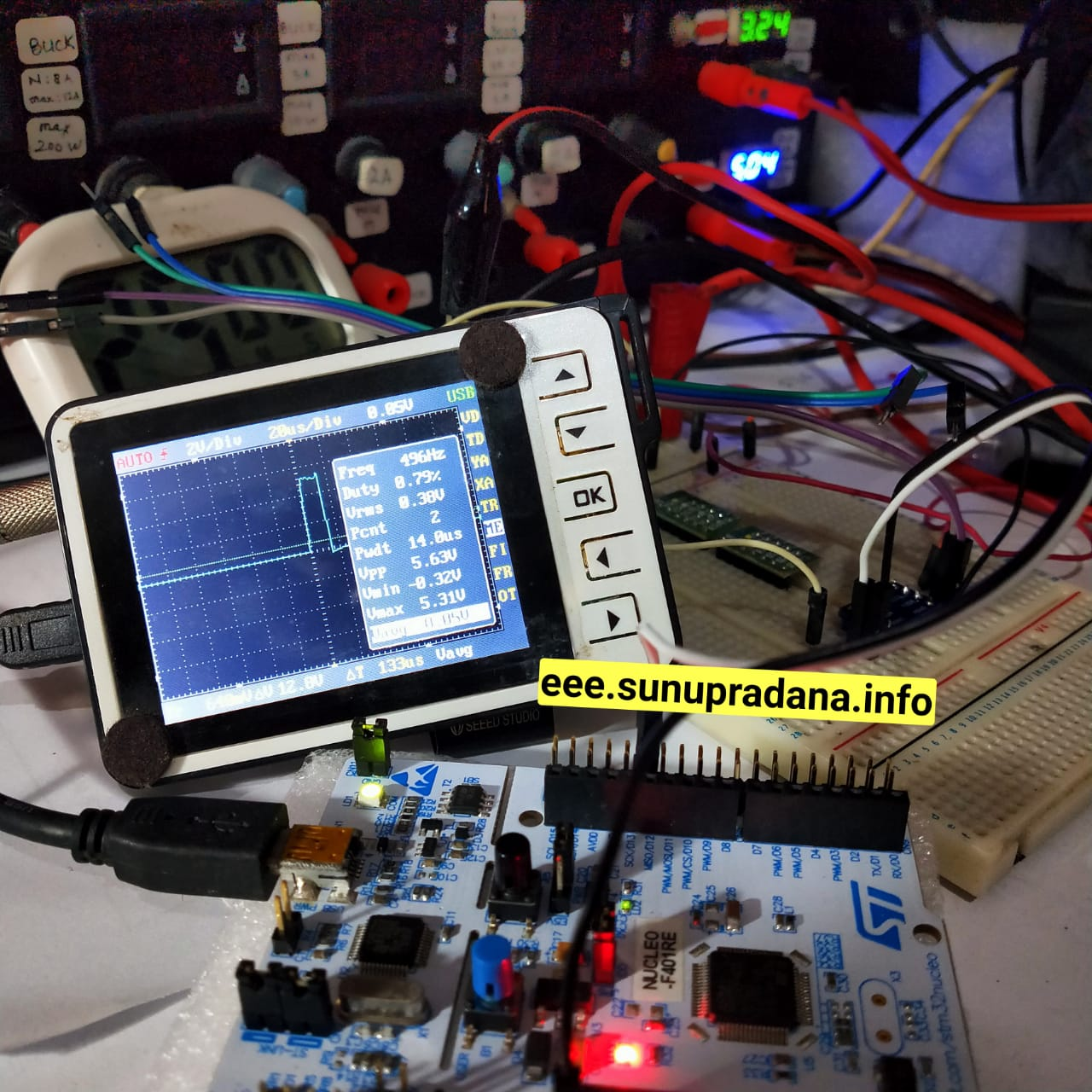
Gambar 8.

Gambar 8 adalah contoh percobaan konversi dari level tegangan sistem digital 3.3 V ke sistem digital 5 V. Sistem sumber yang dipakai adalah yang menggunakan keluarga ARM STM32. Frekuensi diatur mendekati 500 Hz (496 Hz) dengan lebar pulsa high sebesar 14 μS. Hasil konversi akan terlihat seperti di Gambar 9, level tegangan output adalah Vmax 5.31 V atau Vpp 5.63 V menurut alat ukur yang dipakai.

Gambar 9.

[/su_panel] [su_panel border=”3px solid #990066″ radius=”10″] [intense_tabs direction=”right” active_tab_background_color=”#000000″ active_tab_font_color=”#ffff00″ trigger=”click”] [intense_tab title=”Video01″ border=”3px solid #e8e8e8″ link_target=”_self” content_background_color=”#000000″ content_font_color=”#ffffff” icon_size=”1″ icon_position=”left”]

[/intense_tab] [intense_tab title=”Video02″ border=”3px solid #e8e8e8″ link_target=”_self” icon_size=”1″ content_background_color=”#000000″ content_font_color=”#ffffff” icon_position=”left”]

[/intense_tab] [intense_tab title=”Video03″ border=”3px solid #e8e8e8″ link_target=”_self” icon_size=”1″ content_background_color=”#000000″ content_font_color=”#ffffff” icon_position=”left”]

[/intense_tab] [intense_tab title=”Video04″ border=”3px solid #e8e8e8″ link_target=”_self” icon_size=”1″ content_background_color=”#000000″ content_font_color=”#ffffff” icon_position=”left”]

[/intense_tab] [intense_tab title=”Video05″ border=”3px solid #e8e8e8″ link_target=”_self” icon_size=”1″ content_background_color=”#000000″ content_font_color=”#ffffff” icon_position=”left”]

[/intense_tab] [/intense_tabs] [/su_panel]


RTC DS1302

[ [ images & links ] ]
[su_panel border=”3px solid #A13CA6″ radius=”10″]

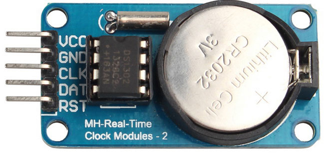
Gambar 1. [sumber]

Sebelumnya, kutipan informasi dari dua RTC telah pernah diungkap di situs ini. Pertama DS1307, dan yang kedua adalah DS3231. Di halaman ini akan saya kutip keterangan mengenai RTC DS1302, yang bersama dua RTC terdahulu saya beli di situs online lokal.


The DS1302 trickle-charge timekeeping chip contains a real-time clock/calendar and 31 bytes of static RAM. It communicates with a microprocessor via a simple serial interface. The real-time clock/calendar provides seconds, minutes, hours, day, date, month, and year information. The end of the month date is automatically adjusted for months with fewer than 31 days, including corrections for leap year. The clock operates in either the 24-hour or 12-hour format with an AM/PM indicator.

Interfacing the DS1302 with a microprocessor is simplified by using synchronous serial communication. Only three wires are required to communicate with the clock/RAM: CE, I/O (data line), and SCLK (serial clock). Data can be transferred to and from the clock/RAM 1 byte at a time or in a burst of up to 31 bytes. The DS1302 is designed to operate on very low power and retain data and clock information on less than 1µW.

The DS1302 is the successor to the DS1202. In addition to the basic timekeeping functions of the DS1202, the DS1302 has the additional features of dual power pins for primary and backup power supplies, programmable trickle charger for VCC1, and seven additional bytes of scratchpad memory.

~maximintegrated.com


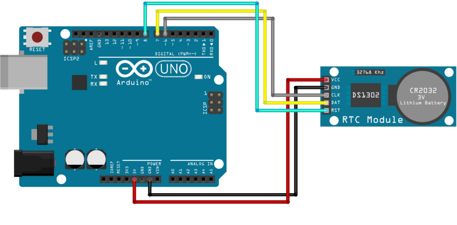
Gambar 2. domoticx.com/arduino-rtc-tijdklok-ds1302/

#include <DS1302.h>

// Init the DS1302
// DS1302 rtc([CE/RST], [I/O], [CLOCK]);
DS1302 rtc(8, 7, 6);

void setup() {
  // Set the clock to run-mode, and disable the write protection
  rtc.halt(false);
  rtc.writeProtect(false);
  
  // Setup Serial connection
  Serial.begin(9600);

  // The following lines can be commented out to use the values already stored in the DS1302
  rtc.setDOW(FRIDAY);        // Set Day-of-Week to FRIDAY
  rtc.setTime(12, 0, 0);     // Set the time to 12:00:00 (24hr format)
  rtc.setDate(6, 8, 2010);   // Set the date to August 6th, 2010
}

void loop() {
  // Send Day-of-Week
  Serial.print(rtc.getDOWStr());
  Serial.print(" ");
  
  // Send date
  Serial.print(rtc.getDateStr());
  Serial.print(" -- ");

  // Send time
  Serial.println(rtc.getTimeStr());
  
  // Wait one second before repeating :)
  delay (1000);
}

Pustaka yang diperlukan untuk mengeksekusi kode bisa diakses di link ini.

[/su_panel] [su_panel border=”3px solid #FF6666″ radius=”10″]

Berdasarkan pengalaman saya menguji coba sistem ini dan pengalaman cukup banyak orang lain yang saya pantau di berbagai halaman di Internet, tampaknya sistem RTC DS1302 yang banyak beredar memiliki permasalahan dalam hal operasi. Banyak pengguna yang melaporkan kesalahan pembacaan jika mempergunakan IC ini. Ada beberapa kemungkinan, termasuk kemungkinan IC yang banyak diperjual-belikan yang memang memiliki grade yang lebih rendah.

Secara praktis, sampai ditemukan solusi yang baik untuk IC ini (versi yang banyak dijual), akan lebih baik mempergunakan RTC DS1307 atau DS3231.
[/su_panel] [su_panel border=”3px solid #990066″ radius=”10″]

[/su_panel]

RTC DS3231

[ [ images, codes & links ] ]
[su_panel border=”3px solid #99BB3D” radius=”10″]

Keterangan mengenai RTC (Real-Time Clock) sudah pernah disampaikan melalui kutipan di post terdahulu. Di halaman itu yang dibahas adalah komponen RTC DS1307, yang lazim diperdagangkan dalam bentuk papan yang ditandai sebagai Tiny RTC. Kali ini saya coba rangkumkan mengenai DS3231 dari berbagai sumber sebagai awalan untuk memperlajarinya. RTC ini dilaporkan memiliki akurasi yang lebih baik dari RTC DS1307.

Gambar 1.


With a backup button cell (e.g. CR2032) on the underside of the module, these DS1307 modules will keep time even when disconnected from the main power source for months and even years on end. However, in our experimental projects (using this RTC with an Arduino for dataloggers amongst other things), we have found these DS1307 modules to vary hugely in their time-keeping accuracy – some gaining/losing a few seconds per day, and others gaining/losing as much as 3-5 minutes per day. While they have proved to be very consistent – i.e. a unit which gains 3 minutes per day will gain 3 minutes per day every day – having to test each unit individually over a few days and then modifying the Arduino project code to cancel out errors is not practical.

Some of the error is caused by ambient temperature changes affecting the accuracy of the timing of the crystal resonator. Some more of the error is also caused by the quality of the crystal itself and its attachment to the PCB in these economical modules.

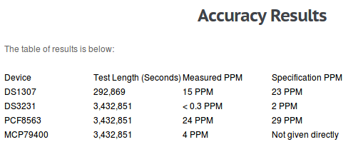
In extensive testing we have found the time-keeping of these modules to be excellent. The DS3231 chip on the module is marketed as being accurate to 2ppm (parts per million), which means less than one second lost or gained every 5 to 6 days. The units we have tested thus far have all come in at under 1ppm accuracy, so a couple of seconds at most lost or gained per month.

This accuracy is achieved in part by the incorporation of a temperature sensor in the DS3231 which can compensate for changes in ambient temperature. The measurements from this temperature sensor are also accessible to the user (accurate to +/- 3 Celcius) which makes for a handy extra feature. These DS3231 modules also have 32kb of available EEPROM memory which can be utilised by your projects, and many other useful features.

~reuk.co.uk


sumber: Benchmarks: Real Time Clocks – Results for Raspberry Pi/Arduino – DS3231 / PCF8563 / MCP79400 / DS1307


Gambar 2. [randomnerdtutorials.com]


[/su_panel] [su_panel border=”3px solid #30C0F0″ radius=”10″]

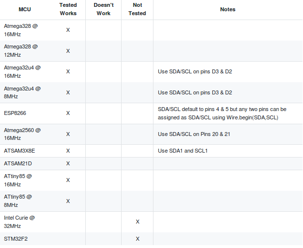
Terdapat beberapa pustaka/library untuk tiap RTC. Dua yang disampaikan dalam “mashup ini adalah pustaka dari Adafruit dan pustaka dari Makuna.

[/su_panel] [su_panel border=”3px solid #FF6666″ radius=”10″]

Contoh-contoh kode program sistem Arduino untuk RTC DS3231.

[/su_panel] [su_panel border=”3px solid #288AC7″ radius=”10″]

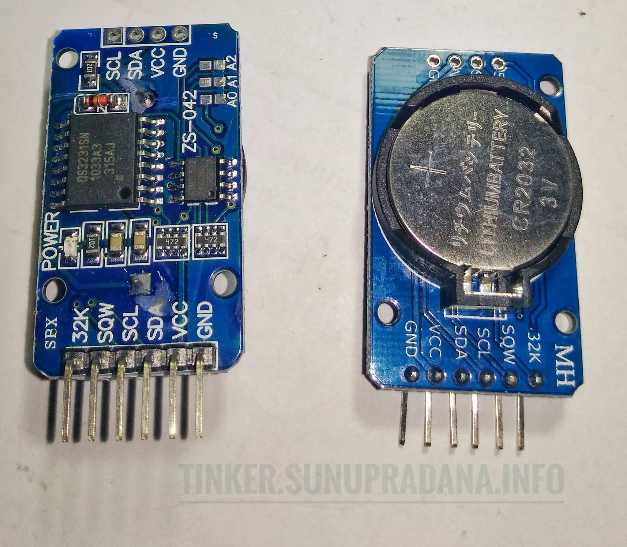
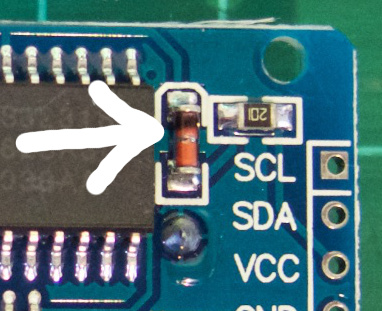
Sistem ini dirancang untuk bekerja dengan menggunakan baterai “khusus”, yaitu baterai yang bisa diisi ulang (rechargeable) seperti LIR2032. Di papan sudah disediakan sistem pengisian ulang untuk baterai tersebut. Karena itu jika kita mempergunakan baterai tipe yang tidak bisa diisi ulang (non-rechargeable) seperti CR2032 maka ada perubahan yang perlu dilakukan. Hal ini untuk mencegah agar baterai primer yang tidak bisa diisi ulang itu tidak berusaha diisi oleh sistem. Caranya adalah dengan melepas/membuang diode seperti pada Gambar 3 berikut.

ds.jpgGambar 3. [sumber: tronixlabs.com]


[/su_panel] [su_panel border=”3px solid #00C700″ radius=”10″] [intense_tabs direction=”right” active_tab_background_color=”#000000″ active_tab_font_color=”#ffff00″ trigger=”click”] [intense_tab title=”Video01″ border=”3px solid #e8e8e8″ link_target=”_self” content_background_color=”#000000″ content_font_color=”#ffffff” icon_size=”1″ icon_position=”left”]

[/intense_tab] [intense_tab title=”Video02″ border=”3px solid #e8e8e8″ link_target=”_self” icon_size=”1″ content_background_color=”#000000″ content_font_color=”#ffffff” icon_position=”left”]

[/intense_tab] [intense_tab title=”Video03″ border=”3px solid #e8e8e8″ link_target=”_self” icon_size=”1″ content_background_color=”#000000″ content_font_color=”#ffffff” icon_position=”left”]

[/intense_tab] [intense_tab title=”Video04″ border=”3px solid #e8e8e8″ link_target=”_self” icon_size=”1″ content_background_color=”#000000″ content_font_color=”#ffffff” icon_position=”left”]

[/intense_tab] [intense_tab title=”Video05″ border=”3px solid #e8e8e8″ link_target=”_self” icon_size=”1″ content_background_color=”#000000″ content_font_color=”#ffffff” icon_position=”left”]

[/intense_tab] [/intense_tabs] [/su_panel] [su_panel border=”3px solid #990066″ radius=”10″] [/su_panel]


Save

RTC DS1307

[ [ images, codes & links ] ]
[su_panel border=”3px solid #5DE800″ radius=”10″]

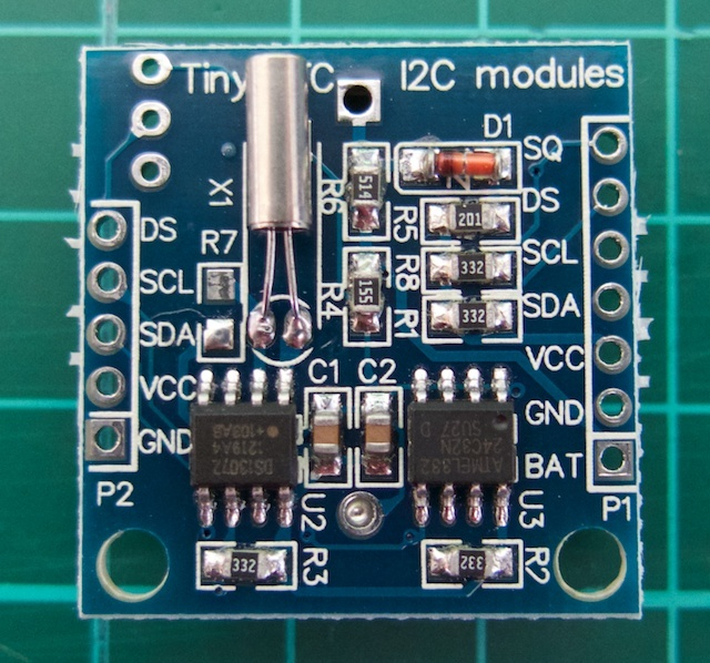
Gambar 1.

A real-time clock (RTC) is a computer clock (most often in the form of an integrated circuit) that keeps track of the current time.

Although the term often refers to the devices in personal computers, servers and embedded systems, RTCs are present in almost any electronic device which needs to keep accurate time.

Real-time clock

What is an RTC?

A real time clock is basically just like a watch – it runs on a battery and keeps time for you even when there is a power outage! Using an RTC, you can keep track of long timelines, even if you reprogram your microcontroller or disconnect it from USB or a power plug.

Most microcontrollers, including the Arduino, have a built-in timekeeper called millis() and there are also timers built into the chip that can keep track of longer time periods like minutes or days. So why would you want to have a separate RTC chip? Well, the biggest reason is that millis() only keeps track of time since the Arduino was last powered – . That means that when the power is turned on, the millisecond timer is set back to 0. The Arduino doesn’t know that it’s ‘Tuesday’ or ‘March 8th’, all it can tell is ‘It’s been 14,000 milliseconds since I was last turned on’.

OK so what if you wanted to set the time on the Arduino? You’d have to program in the date and time and you could have it count from that point on. But if it lost power, you’d have to reset the time. Much like very cheap alarm clocks: every time they lose power they blink 12:00

While this sort of basic timekeeping is OK for some projects, some projects such as data-loggers, clocks, etc will need to have consistent timekeeping that doesn’t reset when the Arduino battery dies or is reprogrammed. Thus, we include a separate RTC! The RTC chip is a specialized chip that just keeps track of time. It can count leap-years and knows how many days are in a month, but it doesn’t take care of Daylight Savings Time (because it changes from place to place).

~DS1307 Real Time Clock Breakout Board Kit


What are Real Time Clocks?

Real time clocks (RTC), as the name recommends are clock modules. The DS1307 real time clock (RTC) IC is an 8 pin device using an I2C interface. The DS1307 is a low-power clock/calendar with 56 bytes of battery backup SRAM. The clock/calendar provides seconds, minutes, hours, day, date, month and year qualified data. The end date of each month is automatically adjusted, especially for months with less than 31 days.

They are available as integrated circuits (ICs) and supervise timing like a clock and also operate date like a calendar. The main advantage of RTC is that they have an arrangement of battery backup which keeps the clock/calendar running even if there is power failure. An exceptionally little current is required for keeping the RTC animated. We can find these RTCs in many applications like embedded systems and computer mother boards, etc.

~www.elprocus.com/rtc-ds1307/


Arduino Tiny RTC D1307 Tutorial


Gambar 2. [henrysbench.capnfatz.com]

Gambar 3. [henrysbench.capnfatz.com]

Gambar 4. [tronixstuff.com]

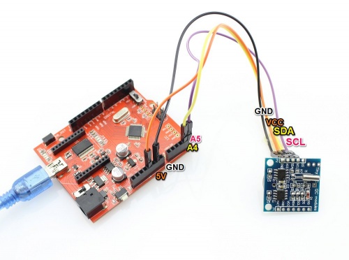
Connecting your module to an Arduino

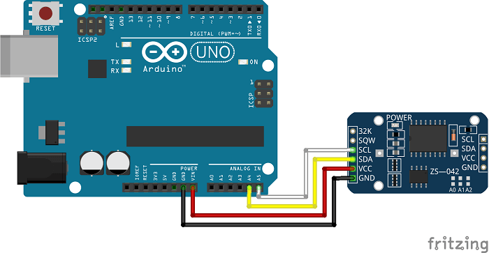
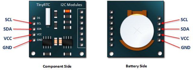
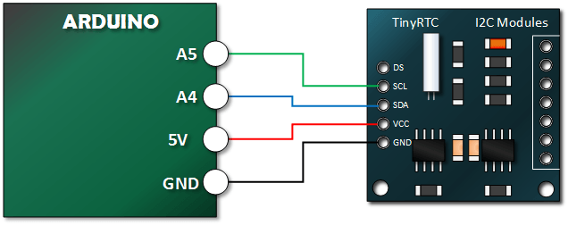
Both modules use the I2C bus, which makes connection very easy. If you’re not sure about the I2C bus and Arduino, check out the I2C tutorials (chapters 20 and 21), or review chapter seventeen of my book “Arduino Workshop“.

Moving on – first you will need to identify which pins on your Arduino or compatible boards are used for the I2C bus – these will be knows as SDA (or data) and SCL (or clock).

~ tronixstuff.com


Tiny RTC

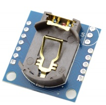
Gambar 5.

Features

  • 5V DC supply
  • Programmable Square-Wave output signal
  • Automatic Power-Fail detect and switch circuitry
  • Consumes less than 500nA in Battery-Backup Mode with Oscillator Running
  • 56-Byte, Battery-Backed, Nonvolatile (NV)RAM for data storage

Gambar 6.

TinyRTC hardware1.jpgGambar 7.

~www.elecrow.com


RTC DS-1307 with Arduino

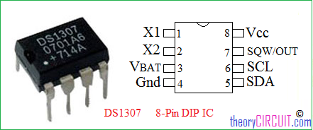
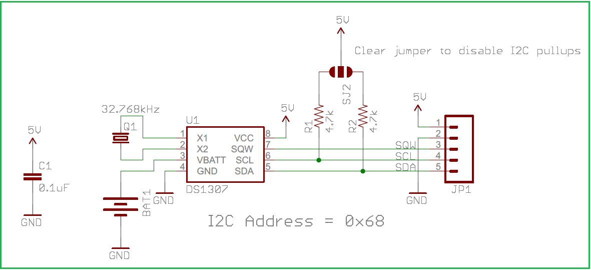
DS 1307 RTC Pinout

Gambar 8.

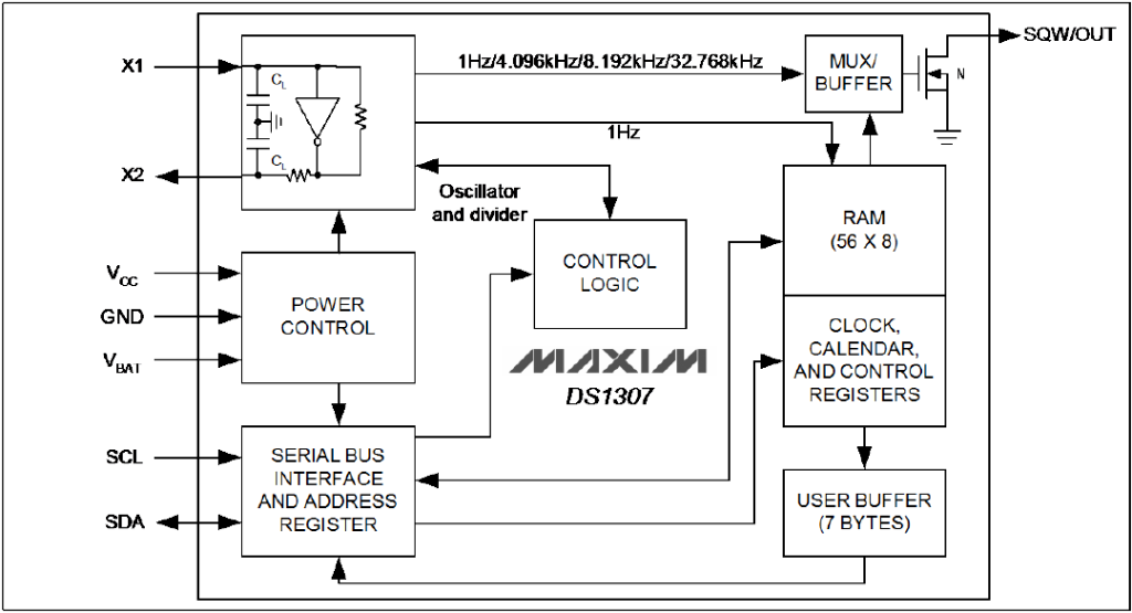
Block Diagram of DS1307

Gambar 9. [Datasheet]

Gambar 10.

~www.theorycircuit.com


[/su_panel] [su_panel border=”3px solid #FFAF24″ radius=”10″]

Terdapat beberapa pustaka/library untuk tiap RTC. Dua yang disampaikan dalam “mashup ini adalah pustaka dari Adafruit dan pustaka dari Makuna.

[/su_panel] [su_panel border=”3px solid #30C0F0″ radius=”10″]

Contoh-contoh kode program sistem Arduino untuk RTC DS1307.

adafruit: ds1307.ino

[code lang=”C”]// Date and time functions using a DS1307 RTC connected via I2C and Wire lib
#include <Wire.h>
#include "RTClib.h"

RTC_DS1307 rtc;

char daysOfTheWeek[7][12] = {"Sunday", "Monday", "Tuesday", "Wednesday", "Thursday", "Friday", "Saturday"};

void setup ()
{
while (!Serial); // for Leonardo/Micro/Zero

// Serial.begin(57600);
Serial.begin(9600);

if (! rtc.begin())
{
Serial.println("Couldn’t find RTC");
while (1);
}

if (! rtc.isrunning())
{
Serial.println("RTC is NOT running!");
// following line sets the RTC to the date &amp; time this sketch was compiled
// rtc.adjust(DateTime(F(__DATE__), F(__TIME__)));
// This line sets the RTC with an explicit date &amp; time, for example to set
// January 21, 2014 at 3am you would call:
// rtc.adjust(DateTime(2014, 1, 21, 3, 0, 0));
}
}

void loop ()
{
DateTime now = rtc.now();

Serial.print(now.year(), DEC);
Serial.print(‘/’);
Serial.print(now.month(), DEC);
Serial.print(‘/’);
Serial.print(now.day(), DEC);
Serial.print(" (");
Serial.print(daysOfTheWeek[now.dayOfTheWeek()]);
Serial.print(") ");
Serial.print(now.hour(), DEC);
Serial.print(‘:’);
Serial.print(now.minute(), DEC);
Serial.print(‘:’);
Serial.print(now.second(), DEC);
Serial.println();

Serial.print(" since midnight 1/1/1970 = ");
Serial.print(now.unixtime());
Serial.print("s = ");
Serial.print(now.unixtime() / 86400L);
Serial.println("d");

// calculate a date which is 7 days and 30 seconds into the future
DateTime future (now + TimeSpan(7,12,30,6));

Serial.print(" now + 7d + 30s: ");
Serial.print(future.year(), DEC);
Serial.print(‘/’);
Serial.print(future.month(), DEC);
Serial.print(‘/’);
Serial.print(future.day(), DEC);
Serial.print(‘ ‘);
Serial.print(future.hour(), DEC);
Serial.print(‘:’);
Serial.print(future.minute(), DEC);
Serial.print(‘:’);
Serial.print(future.second(), DEC);
Serial.println();

Serial.println();
delay(3000);
}[/code]

[/su_panel] [su_panel border=”3px solid #D8DA36″ radius=”10″] [intense_tabs direction=”right” active_tab_background_color=”#000000″ active_tab_font_color=”#ffff00″ trigger=”click”] [intense_tab title=”Video01″ border=”3px solid #e8e8e8″ link_target=”_self” content_background_color=”#000000″ content_font_color=”#ffffff” icon_size=”1″ icon_position=”left”]

[/intense_tab] [intense_tab title=”Video02″ border=”3px solid #e8e8e8″ link_target=”_self” icon_size=”1″ content_background_color=”#000000″ content_font_color=”#ffffff” icon_position=”left”]

[/intense_tab] [intense_tab title=”Video03″ border=”3px solid #e8e8e8″ link_target=”_self” icon_size=”1″ content_background_color=”#000000″ content_font_color=”#ffffff” icon_position=”left”]

[/intense_tab] [intense_tab title=”Video04″ border=”3px solid #e8e8e8″ link_target=”_self” icon_size=”1″ content_background_color=”#000000″ content_font_color=”#ffffff” icon_position=”left”]

[/intense_tab] [/intense_tabs] [/su_panel] [su_panel border=”3px solid #990066″ radius=”10″] [/su_panel]


IR infrared remote control dengan Arduino

[ [ images & links ] ]
[su_panel border=”3px solid #37CCAE” radius=”10″]

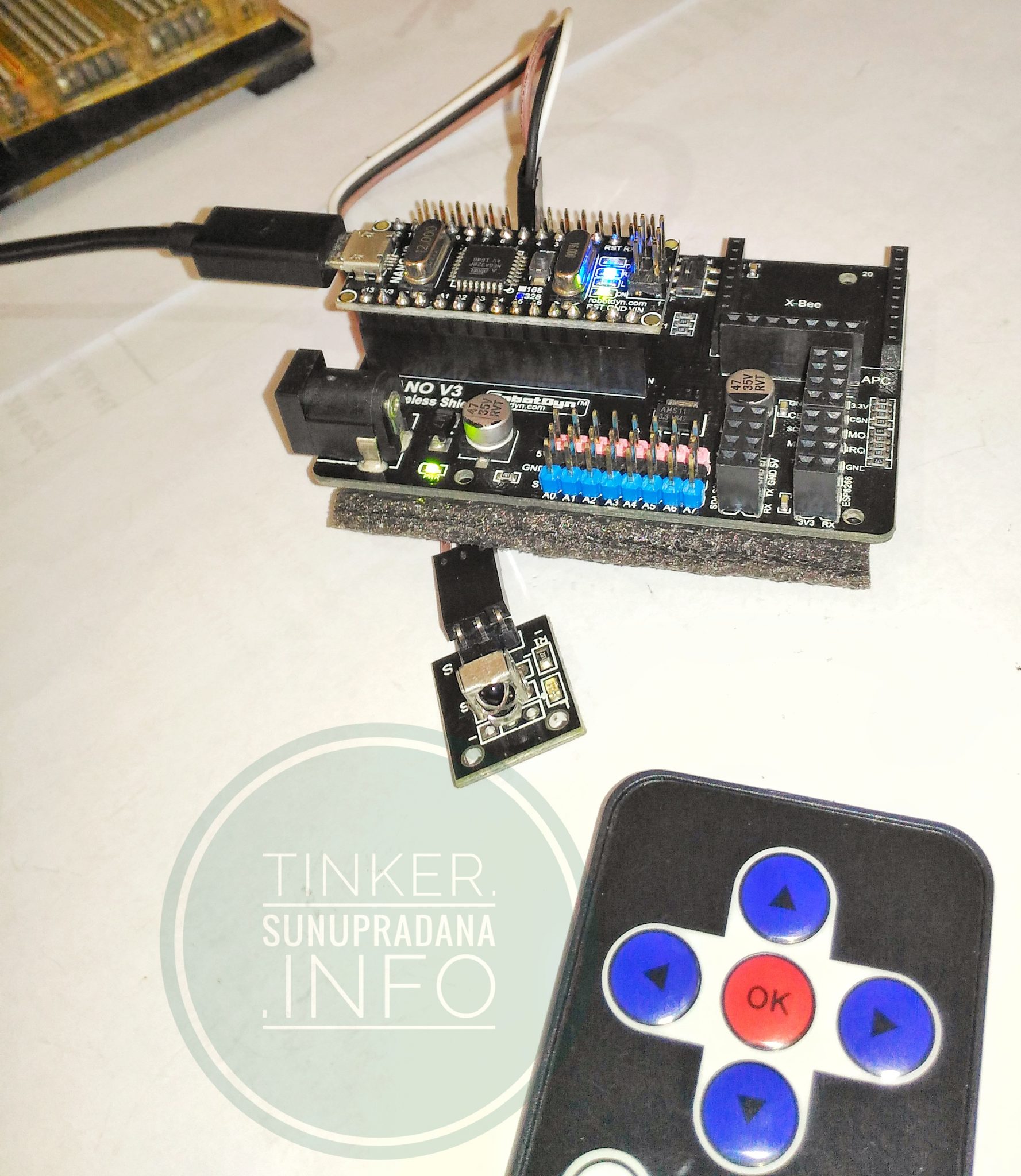
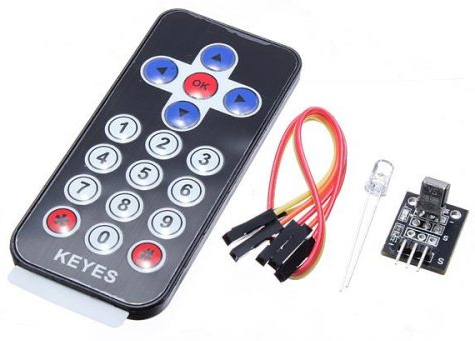
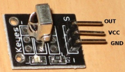
Gambar 1. [sumber]

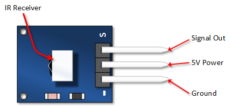
Gambar 2. [sumber]

Infrared IR Receiver Module Wireless Remote Control Kit For Arduino

Description:

Arduino mini infrared wireless remote control kit consists of ultra-thin infrared remote control and 38KHz infrared receiver module. This mini slim infrared remote control with 20 function keys. Its transmit distances up to 8 meters. Ideal for handling a variety of equipment indoors.
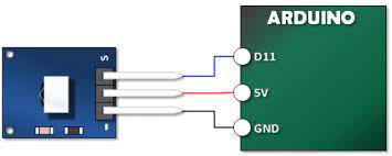
IR receiver module can receive standard 38KHz modulation remote control signal. You can decode the remote control signal through Arduino programming. You can design a variety of remote control robots and interactive works.

Specification:

Transmission distance: up to 8m(depending on the surrounding environment, sensitivity of receiver etc)
Battery: CR2025 button battery
Battery capacity: 160mAh
Effective angle: 60°
Sticking material: 0.125mmPET
Effective life: 20,000 times
Static current: 3uA – 5uA
Dynamic current: 3mA – 5mA

~alexnld.com

MAKER Version Electronic Brick Set IR Remote

The IR Remote supplied with this Set looks like this (Others may also be supplied):

– Based on NEC protocol; Built-in 1 x AG10 battery;
– Remote control range: above 8m;
– Wavelength: 940Nm;
– Frequency: crystal oscillator: 455KHz; IR carrier frequency: 38KHz

This is especially good for remote control of a small robot, using the arrow buttons. Below is [ps2id url=’#terryyourduino’ offset=’300′]an example Software Sketch[/ps2id] for this remote. The reported buttons will be Forward, Left, Right, Reverse (for the 4 blue button), OK for the red ‘OK’ button, 1 to 0 for the white number buttons, and ‘*’ and ‘#’ for the bottom red buttons.

TYPES OF IR REMOTE CONTROLS
NOTE!! Most handheld remotes are shipped with a small clear plastic piece in the battery compartment that must be removed to activate it. You can usually just pull it out.
There are many different IR remote controls. Some from YourDuino.com are the low-cost IR Infrared Remote Control Kit 2 and also the THIS IR Remote (right) which has directional buttons that would be good for controlling a vehicle etc. Then, there are the typical TV and Stereo Remotes. All of these may have different encoding methods and number of physical buttons, and different codes received when a button is pressed. Below we will give [ps2id url=’#terryyourduino’ offset=’300′]example Software Sketches[/ps2id] for a few common IR Remotes.

IR-REMOTE LIBRARY:
Note: The following library must be installed in your Arduino installation for this to work!
CLICK HERE – IR REMOTE CONTROL: ARDUINO LIBRARY

NOTE!! If you have a late version of Arduino with a library IRRobotRemote, it may conflict and you may have to remove that library.
Make sure to delete Arduino_Root/libraries/RobotIRremote. Where Arduino_Root refers to the install directory of Arduino. The library RobotIRremote has similar definitions to IRremote and causes errors.

~arduino-info.wikispaces.com/IR-RemoteControl

Gambar 3. [sumber]

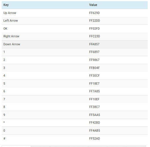
Gambar 4. [sumber]

Contoh salah satu tabel output dari IR remote control (cocok untuk IR RC Keyes warna hitam dengan tombol arah).

Untuk contoh kode lihat di [ps2id url=’#xindacode’ offset=’350′] bagian halaman ini.[/ps2id] [/su_panel] [su_panel border=”3px solid #30C0F0″ radius=”10″]

z3t0/Arduino-IRremote

[/su_panel] [su_panel border=”3px solid #FF6666″ radius=”10″]

Receiving and printing a code:

The following sketch will receive codes and print them to the serial port. This sketch is very useful for testing IR receiving, and for determining what code values to use in your code. A slightly more complex version is in the examples directory as IRrecvDump.

This sketch also illustrates how to perform an action while a button is pressed. In this example, the action is writing to the serial port.

#include <IRremote.h>
IRrecv irrecv(7); // Receive on pin 7
decode_results results;

void setup()
{
  Serial.begin(9600);
  irrecv.enableIRIn(); // Start the receiver
}

void loop() 
{
  if (irrecv.decode(&results)) 
  {
    Serial.println(results.value, HEX);
    irrecv.resume(); // Continue receiving
  }
}


IRrecvDemo.ino

/*
 * IRremote: IRrecvDemo - demonstrates receiving IR codes with IRrecv
 * An IR detector/demodulator must be connected to the input RECV_PIN.
 * Version 0.1 July, 2009
 * Copyright 2009 Ken Shirriff
 * http://arcfn.com
 */

#include <IRremote.h>

int RECV_PIN = 7;

IRrecv irrecv(RECV_PIN);

decode_results results;

void setup()
{
  Serial.begin(9600);
  // In case the interrupt driver crashes on setup, give a clue
  // to the user what's going on.
  Serial.println("Enabling IRin");
  irrecv.enableIRIn(); // Start the receiver
  Serial.println("Enabled IRin");
}

void loop() 
{
  if (irrecv.decode(&results)) 
  {
    Serial.println(results.value, HEX);
    irrecv.resume(); // Receive the next value
  }
  delay(100);
}

IRrecvDump.ino

/*
 * IRremote: IRrecvDump - dump details of IR codes with IRrecv
 * An IR detector/demodulator must be connected to the input RECV_PIN.
 * Version 0.1 July, 2009
 * Copyright 2009 Ken Shirriff
 * http://arcfn.com
 * JVC and Panasonic protocol added by Kristian Lauszus (Thanks to zenwheel and other people at the original blog post)
 * LG added by Darryl Smith (based on the JVC protocol)
 */

#include <IRremote.h>

/* 
*  Default is Arduino pin D11. 
*  You can change this to another available Arduino Pin.
*  Your IR receiver should be connected to the pin defined here
*/
int RECV_PIN = 7;

IRrecv irrecv(RECV_PIN);

decode_results results;

void setup()
{
  Serial.begin(9600);
  irrecv.enableIRIn(); // Start the receiver
}


void dump(decode_results *results) {
  // Dumps out the decode_results structure.
  // Call this after IRrecv::decode()
  int count = results->rawlen;
  if (results->decode_type == UNKNOWN) {
    Serial.print("Unknown encoding: ");
  }
  else if (results->decode_type == NEC) {
    Serial.print("Decoded NEC: ");

  }
  else if (results->decode_type == SONY) {
    Serial.print("Decoded SONY: ");
  }
  else if (results->decode_type == RC5) {
    Serial.print("Decoded RC5: ");
  }
  else if (results->decode_type == RC6) {
    Serial.print("Decoded RC6: ");
  }
  else if (results->decode_type == PANASONIC) {
    Serial.print("Decoded PANASONIC - Address: ");
    Serial.print(results->address, HEX);
    Serial.print(" Value: ");
  }
  else if (results->decode_type == LG) {
    Serial.print("Decoded LG: ");
  }
  else if (results->decode_type == JVC) {
    Serial.print("Decoded JVC: ");
  }
  else if (results->decode_type == AIWA_RC_T501) {
    Serial.print("Decoded AIWA RC T501: ");
  }
  else if (results->decode_type == WHYNTER) {
    Serial.print("Decoded Whynter: ");
  }
  Serial.print(results->value, HEX);
  Serial.print(" (");
  Serial.print(results->bits, DEC);
  Serial.println(" bits)");
  Serial.print("Raw (");
  Serial.print(count, DEC);
  Serial.print("): ");

  for (int i = 1; i < count; i++) {
    if (i & 1) {
      Serial.print(results->rawbuf[i]*USECPERTICK, DEC);
    }
    else {
      Serial.write('-');
      Serial.print((unsigned long) results->rawbuf[i]*USECPERTICK, DEC);
    }
    Serial.print(" ");
  }
  Serial.println();
}

void loop() {
  if (irrecv.decode(&results)) {
    Serial.println(results.value, HEX);
    dump(&results);
    irrecv.resume(); // Receive the next value
  }
}

Arduino Keyes / Xinda IR Remote Control Tutorial

IR Remote Tutorial Code Part 2

//  Henry's Bench IR Remote Tutorial 2

#include <IRremote.h>

int IR_PIN = 7;

IRrecv irDetect(IR_PIN);

decode_results irIn;

void setup()
{
  Serial.begin(9600);
  
  irDetect.enableIRIn(); // Start the Receiver
}

void loop() {
  if (irDetect.decode(&irIn)) {
    decodeIR();
    irDetect.resume(); 
  }
}

void decodeIR() // Indicate what key is pressed

{

  switch(irIn.value)

  {

  case 0xFF629D:  
    Serial.println("Up Arrow"); 
    break;

  case 0xFF22DD:  
    Serial.println("Left Arrow"); 
    break;

  case 0xFF02FD:  
    Serial.println("OK"); 
    break;

  case 0xFFC23D:  
    Serial.println("Right Arrow"); 
    break;

  case 0xFFA857:  
    Serial.println("Down Arrow"); 
    break;

  case 0xFF6897:  
    Serial.println("1"); 
    break;

  case 0xFF9867:  
    Serial.println("2"); 
    break;

  case 0xFFB04F:  
    Serial.println("3"); 
    break;

  case 0xFF30CF:  
    Serial.println("4"); 
    break;

  case 0xFF18E7:  
    Serial.println("5"); 
    break;

  case 0xFF7A85:  
    Serial.println("6"); 
    break;

  case 0xFF10EF:  
    Serial.println("7"); 
    break;

  case 0xFF38C7:  
    Serial.println("8"); 
    break;

  case 0xFF5AA5:  
    Serial.println("9"); 
    break;

  case 0xFF42BD:  
    Serial.println("*"); 
    break;

  case 0xFF4AB5:  
    Serial.println("0"); 
    break;

  case 0xFF52AD:  
    Serial.println("#"); 
    break; 

  default: 
   break;

  }
}

https://arduino-info.wikispaces.com/IR-RemoteControl  

/* YourDuino.com Example Software Sketch
 Brick Starter Set IR Remote Kit Test
http://yourduino.com/sunshop2/index.php?l=product_detail&p=364
 based on code by Ken Shirriff - http://arcfn.com
 Get Library at: https://github.com/shirriff/Arduino-IRremote
 Unzip folder into Libraries. RENAME folder IRremote
 terry@yourduino.com */

/*-----( Import needed libraries )-----*/

#include "IRremote.h"

/*-----( Declare Constants )-----*/
int receiver = 7; // pin 1 of IR receiver to Arduino digital pin 7

/*-----( Declare objects )-----*/
IRrecv irrecv(receiver);           // create instance of 'irrecv'
decode_results results;            // create instance of 'decode_results'
/*-----( Declare Variables )-----*/


void setup()   /*----( SETUP: RUNS ONCE )----*/
{
  Serial.begin(9600);
  Serial.println("YourDuino IR Receiver Button Decode Test");
  Serial.println("Questions: terry@yourduino.com");  
  irrecv.enableIRIn(); // Start the receiver

}/*--(end setup )---*/


void loop()   /*----( LOOP: RUNS CONSTANTLY )----*/
{
  if (irrecv.decode(&results)) // have we received an IR signal?

  {
//    Serial.println(results.value, HEX);  UN Comment to see raw values
    translateIR(); 
    irrecv.resume(); // receive the next value
  }  
}/* --(end main loop )-- */

/*-----( Declare User-written Functions )-----*/
void translateIR() // takes action based on IR code received

// describing KEYES Remote IR codes 

{

  switch(results.value)

  {

  case 0xFF629D: Serial.println(" FORWARD"); break;
  case 0xFF22DD: Serial.println(" LEFT");    break;
  case 0xFF02FD: Serial.println(" -OK-");    break;
  case 0xFFC23D: Serial.println(" RIGHT");   break;
  case 0xFFA857: Serial.println(" REVERSE"); break;
  case 0xFF6897: Serial.println(" 1");    break;
  case 0xFF9867: Serial.println(" 2");    break;
  case 0xFFB04F: Serial.println(" 3");    break;
  case 0xFF30CF: Serial.println(" 4");    break;
  case 0xFF18E7: Serial.println(" 5");    break;
  case 0xFF7A85: Serial.println(" 6");    break;
  case 0xFF10EF: Serial.println(" 7");    break;
  case 0xFF38C7: Serial.println(" 8");    break;
  case 0xFF5AA5: Serial.println(" 9");    break;
  case 0xFF42BD: Serial.println(" *");    break;
  case 0xFF4AB5: Serial.println(" 0");    break;
  case 0xFF52AD: Serial.println(" #");    break;
  case 0xFFFFFFFF: Serial.println(" REPEAT");break;  

  default: 
    Serial.println(" other button   ");

  }// End Case

  delay(500); // Do not get immediate repeat


} //END translateIR

/* ( THE END ) */

Gambar 5.

[/su_panel] [su_panel border=”3px solid #00C700″ radius=”10″] [intense_tabs direction=”right” active_tab_background_color=”#000000″ active_tab_font_color=”#ffff00″ trigger=”click”] [intense_tab title=”Video01″ border=”3px solid #e8e8e8″ link_target=”_self” content_background_color=”#000000″ content_font_color=”#ffffff” icon_size=”1″ icon_position=”left”]

[/intense_tab] [intense_tab title=”Video02″ border=”3px solid #e8e8e8″ link_target=”_self” icon_size=”1″ content_background_color=”#000000″ content_font_color=”#ffffff” icon_position=”left”]

[/intense_tab] [intense_tab title=”Video03″ border=”3px solid #e8e8e8″ link_target=”_self” icon_size=”1″ content_background_color=”#000000″ content_font_color=”#ffffff” icon_position=”left”]

[/intense_tab] [intense_tab title=”Video04″ border=”3px solid #e8e8e8″ link_target=”_self” icon_size=”1″ content_background_color=”#000000″ content_font_color=”#ffffff” icon_position=”left”]

[/intense_tab] [intense_tab title=”Video05″ border=”3px solid #e8e8e8″ link_target=”_self” icon_size=”1″ content_background_color=”#000000″ content_font_color=”#ffffff” icon_position=”left”]

[/intense_tab] [/intense_tabs] [/su_panel] [su_panel border=”3px solid #990066″ radius=”10″] [/su_panel]