 Gambar 1. [sumber]
 Gambar 2. [sumber]
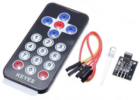
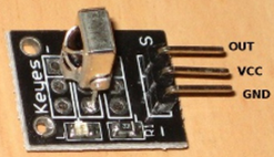
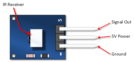
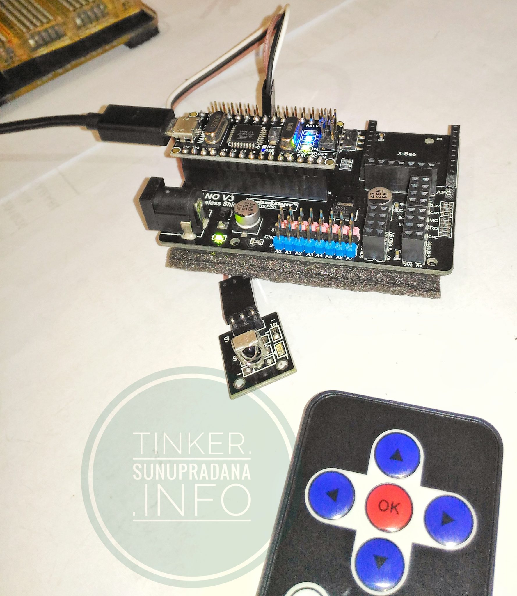
Infrared IR Receiver Module Wireless Remote Control Kit For Arduino
Description:
Arduino mini infrared wireless remote control kit consists of ultra-thin infrared remote control and 38KHz infrared receiver module. This mini slim infrared remote control with 20 function keys. Its transmit distances up to 8 meters. Ideal for handling a variety of equipment indoors.
IR receiver module can receive standard 38KHz modulation remote control signal. You can decode the remote control signal through Arduino programming. You can design a variety of remote control robots and interactive works.Specification:
Transmission distance: up to 8m(depending on the surrounding environment, sensitivity of receiver etc)
Battery: CR2025 button battery
Battery capacity: 160mAh
Effective angle: 60°
Sticking material: 0.125mmPET
Effective life: 20,000 times
Static current: 3uA – 5uA
Dynamic current: 3mA – 5mA
MAKER Version Electronic Brick Set IR Remote
The IR Remote supplied with this Set looks like this (Others may also be supplied):
- Based on NEC protocol; Built-in 1 x AG10 battery;
- Remote control range: above 8m;
- Wavelength: 940Nm;
- Frequency: crystal oscillator: 455KHz; IR carrier frequency: 38KHzThis is especially good for remote control of a small robot, using the arrow buttons. Below is [ps2id url=’#terryyourduino’ offset=’300′]an example Software Sketch[/ps2id] for this remote. The reported buttons will be Forward, Left, Right, Reverse (for the 4 blue button), OK for the red ‘OK’ button, 1 to 0 for the white number buttons, and ‘*’ and ‘#’ for the bottom red buttons.
TYPES OF IR REMOTE CONTROLS
NOTE!! Most handheld remotes are shipped with a small clear plastic piece in the battery compartment that must be removed to activate it. You can usually just pull it out.
There are many different IR remote controls. Some from YourDuino.com are the low-cost IR Infrared Remote Control Kit 2 and also the THIS IR Remote(right)which has directional buttons that would be good for controlling a vehicle etc. Then, there are the typical TV and Stereo Remotes. All of these may have different encoding methods and number of physical buttons, and different codes received when a button is pressed. Below we will give [ps2id url=’#terryyourduino’ offset=’300′]example Software Sketches[/ps2id] for a few common IR Remotes.IR-REMOTE LIBRARY:
Note: The following library must be installed in your Arduino installation for this to work!
CLICK HERE - IR REMOTE CONTROL: ARDUINO LIBRARYNOTE!! If you have a late version of Arduino with a library IRRobotRemote, it may conflict and you may have to remove that library.
Make sure to delete Arduino_Root/libraries/RobotIRremote. Where Arduino_Root refers to the install directory of Arduino. The library RobotIRremote has similar definitions to IRremote and causes errors.
 Gambar 3. [sumber]
 Gambar 4. [sumber]
Contoh salah satu tabel output dari IR remote control (cocok untuk IR RC Keyes warna hitam dengan tombol arah).
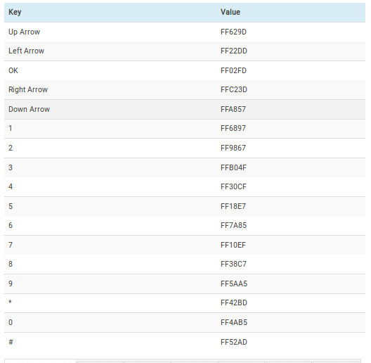
Untuk contoh kode lihat di [ps2id url=’#xindacode’ offset=’350′] bagian halaman ini.[/ps2id] [/su_panel] [su_panel border=”3px solid #30C0F0″ radius=”10″]
z3t0/Arduino-IRremote
Receiving and printing a code:
The following sketch will receive codes and print them to the serial port. This sketch is very useful for testing IR receiving, and for determining what code values to use in your code. A slightly more complex version is in the examples directory as IRrecvDump.
This sketch also illustrates how to perform an action while a button is pressed. In this example, the action is writing to the serial port.
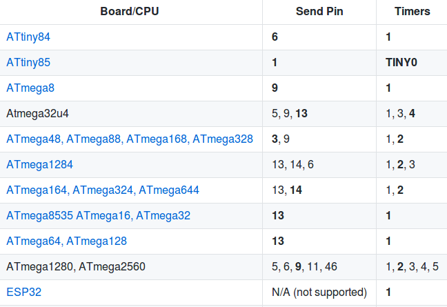
#include <IRremote.h>
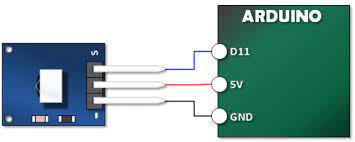
IRrecv irrecv(7); // Receive on pin 7
decode_results results;
void setup()
{
Serial.begin(9600);
irrecv.enableIRIn(); // Start the receiver
}
void loop()
{
if (irrecv.decode(&results))
{
Serial.println(results.value, HEX);
irrecv.resume(); // Continue receiving
}
}
/*
 * IRremote: IRrecvDemo - demonstrates receiving IR codes with IRrecv
 * An IR detector/demodulator must be connected to the input RECV_PIN.
 * Version 0.1 July, 2009
 * Copyright 2009 Ken Shirriff
 * http://arcfn.com
 */
#include <IRremote.h>
int RECV_PIN = 7;
IRrecv irrecv(RECV_PIN);
decode_results results;
void setup()
{
  Serial.begin(9600);
  // In case the interrupt driver crashes on setup, give a clue
  // to the user what's going on.
  Serial.println("Enabling IRin");
  irrecv.enableIRIn(); // Start the receiver
  Serial.println("Enabled IRin");
}
void loop()
{
  if (irrecv.decode(&results))
  {
    Serial.println(results.value, HEX);
    irrecv.resume(); // Receive the next value
  }
  delay(100);
}
/*
 * IRremote: IRrecvDump - dump details of IR codes with IRrecv
 * An IR detector/demodulator must be connected to the input RECV_PIN.
 * Version 0.1 July, 2009
 * Copyright 2009 Ken Shirriff
 * http://arcfn.com
 * JVC and Panasonic protocol added by Kristian Lauszus (Thanks to zenwheel and other people at the original blog post)
 * LG added by Darryl Smith (based on the JVC protocol)
 */
#include <IRremote.h>
/*
*  Default is Arduino pin D11.
*  You can change this to another available Arduino Pin.
*  Your IR receiver should be connected to the pin defined here
*/
int RECV_PIN = 7;
IRrecv irrecv(RECV_PIN);
decode_results results;
void setup()
{
  Serial.begin(9600);
  irrecv.enableIRIn(); // Start the receiver
}
void dump(decode_results *results) {
  // Dumps out the decode_results structure.
  // Call this after IRrecv::decode()
  int count = results->rawlen;
  if (results->decode_type == UNKNOWN) {
    Serial.print("Unknown encoding: ");
  }
  else if (results->decode_type == NEC) {
    Serial.print("Decoded NEC: ");
  }
  else if (results->decode_type == SONY) {
    Serial.print("Decoded SONY: ");
  }
  else if (results->decode_type == RC5) {
    Serial.print("Decoded RC5: ");
  }
  else if (results->decode_type == RC6) {
    Serial.print("Decoded RC6: ");
  }
  else if (results->decode_type == PANASONIC) {
    Serial.print("Decoded PANASONIC - Address: ");
    Serial.print(results->address, HEX);
    Serial.print(" Value: ");
  }
  else if (results->decode_type == LG) {
    Serial.print("Decoded LG: ");
  }
  else if (results->decode_type == JVC) {
    Serial.print("Decoded JVC: ");
  }
  else if (results->decode_type == AIWA_RC_T501) {
    Serial.print("Decoded AIWA RC T501: ");
  }
  else if (results->decode_type == WHYNTER) {
    Serial.print("Decoded Whynter: ");
  }
  Serial.print(results->value, HEX);
  Serial.print(" (");
  Serial.print(results->bits, DEC);
  Serial.println(" bits)");
  Serial.print("Raw (");
  Serial.print(count, DEC);
  Serial.print("): ");
  for (int i = 1; i < count; i++) {
    if (i & 1) {
      Serial.print(results->rawbuf[i]*USECPERTICK, DEC);
    }
    else {
      Serial.write('-');
      Serial.print((unsigned long) results->rawbuf[i]*USECPERTICK, DEC);
    }
    Serial.print(" ");
  }
  Serial.println();
}
void loop() {
  if (irrecv.decode(&results)) {
    Serial.println(results.value, HEX);
    dump(&results);
    irrecv.resume(); // Receive the next value
  }
}
Arduino Keyes / Xinda IR Remote Control Tutorial
IR Remote Tutorial Code Part 2
//  Henry's Bench IR Remote Tutorial 2
#include <IRremote.h>
int IR_PIN = 7;
IRrecv irDetect(IR_PIN);
decode_results irIn;
void setup()
{
  Serial.begin(9600);
  irDetect.enableIRIn(); // Start the Receiver
}
void loop() {
  if (irDetect.decode(&irIn)) {
    decodeIR();
    irDetect.resume();
  }
}
void decodeIR() // Indicate what key is pressed
{
  switch(irIn.value)
  {
  case 0xFF629D:
    Serial.println("Up Arrow");
    break;
  case 0xFF22DD:
    Serial.println("Left Arrow");
    break;
  case 0xFF02FD:
    Serial.println("OK");
    break;
  case 0xFFC23D:
    Serial.println("Right Arrow");
    break;
  case 0xFFA857:
    Serial.println("Down Arrow");
    break;
  case 0xFF6897:
    Serial.println("1");
    break;
  case 0xFF9867:
    Serial.println("2");
    break;
  case 0xFFB04F:
    Serial.println("3");
    break;
  case 0xFF30CF:
    Serial.println("4");
    break;
  case 0xFF18E7:
    Serial.println("5");
    break;
  case 0xFF7A85:
    Serial.println("6");
    break;
  case 0xFF10EF:
    Serial.println("7");
    break;
  case 0xFF38C7:
    Serial.println("8");
    break;
  case 0xFF5AA5:
    Serial.println("9");
    break;
  case 0xFF42BD:
    Serial.println("*");
    break;
  case 0xFF4AB5:
    Serial.println("0");
    break;
  case 0xFF52AD:
    Serial.println("#");
    break;
  default:
   break;
  }
}
https://arduino-info.wikispaces.com/IR-RemoteControl
/* YourDuino.com Example Software Sketch
 Brick Starter Set IR Remote Kit Test
http://yourduino.com/sunshop2/index.php?l=product_detail&p;=364
 based on code by Ken Shirriff - http://arcfn.com
 Get Library at: https://github.com/shirriff/Arduino-IRremote
 Unzip folder into Libraries. RENAME folder IRremote
 [email protected] */
/*-----( Import needed libraries )-----*/
#include "IRremote.h"
/*-----( Declare Constants )-----*/
int receiver = 7; // pin 1 of IR receiver to Arduino digital pin 7
/*-----( Declare objects )-----*/
IRrecv irrecv(receiver);           // create instance of 'irrecv'
decode_results results;            // create instance of 'decode_results'
/*-----( Declare Variables )-----*/
void setup()   /*----( SETUP: RUNS ONCE )----*/
{
  Serial.begin(9600);
  Serial.println("YourDuino IR Receiver Button Decode Test");
  Serial.println("Questions: [email protected]");
  irrecv.enableIRIn(); // Start the receiver
}/*--(end setup )---*/
void loop()   /*----( LOOP: RUNS CONSTANTLY )----*/
{
  if (irrecv.decode(&results)) // have we received an IR signal?
  {
//    Serial.println(results.value, HEX);  UN Comment to see raw values
    translateIR();
    irrecv.resume(); // receive the next value
  }
}/* --(end main loop )-- */
/*-----( Declare User-written Functions )-----*/
void translateIR() // takes action based on IR code received
// describing KEYES Remote IR codes
{
  switch(results.value)
  {
  case 0xFF629D: Serial.println(" FORWARD"); break;
  case 0xFF22DD: Serial.println(" LEFT");    break;
  case 0xFF02FD: Serial.println(" -OK-");    break;
  case 0xFFC23D: Serial.println(" RIGHT");   break;
  case 0xFFA857: Serial.println(" REVERSE"); break;
  case 0xFF6897: Serial.println(" 1");    break;
  case 0xFF9867: Serial.println(" 2");    break;
  case 0xFFB04F: Serial.println(" 3");    break;
  case 0xFF30CF: Serial.println(" 4");    break;
  case 0xFF18E7: Serial.println(" 5");    break;
  case 0xFF7A85: Serial.println(" 6");    break;
  case 0xFF10EF: Serial.println(" 7");    break;
  case 0xFF38C7: Serial.println(" 8");    break;
  case 0xFF5AA5: Serial.println(" 9");    break;
  case 0xFF42BD: Serial.println(" *");    break;
  case 0xFF4AB5: Serial.println(" 0");    break;
  case 0xFF52AD: Serial.println(" #");    break;
  case 0xFFFFFFFF: Serial.println(" REPEAT");break;
  default:
    Serial.println(" other button   ");
  }// End Case
  delay(500); // Do not get immediate repeat
} //END translateIR
/* ( THE END ) */
 Gambar 5.
 Gambar 1.
 Gambar 2.
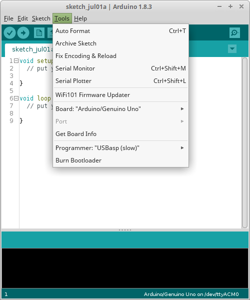 Gambar 3.
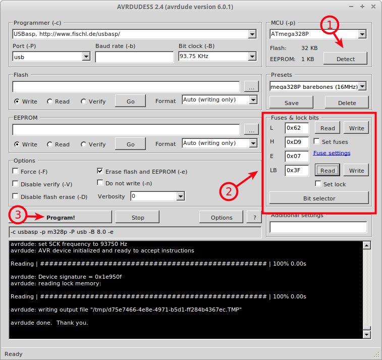
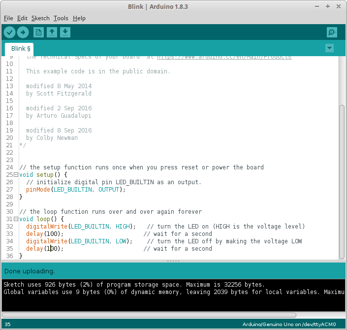 Gambar 7. Uji coba bootloader yang baru diisikan pada Arduino Uno
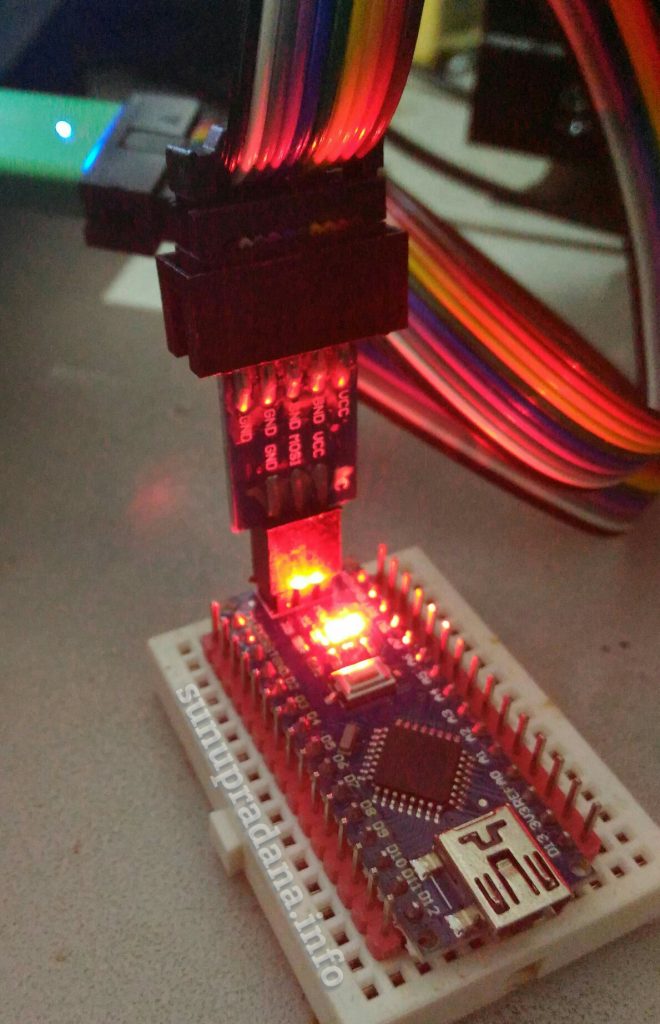
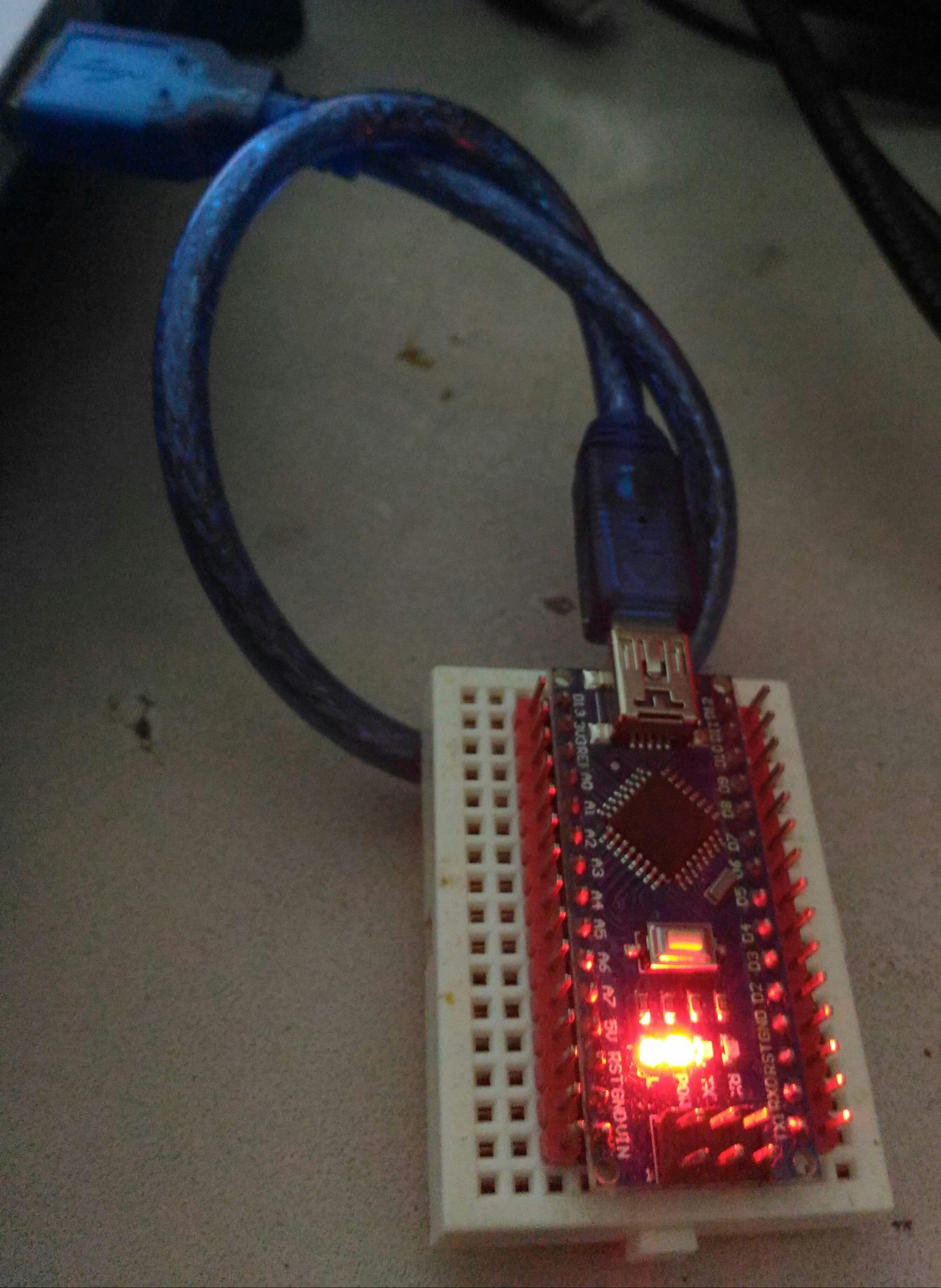
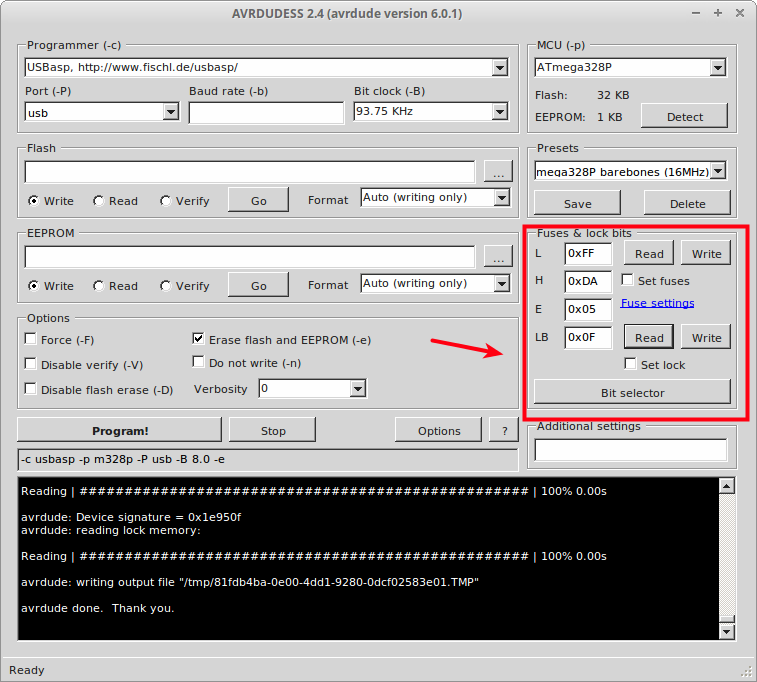 Gambar 8. Kondisi awal Arduino Nano ATmega328P
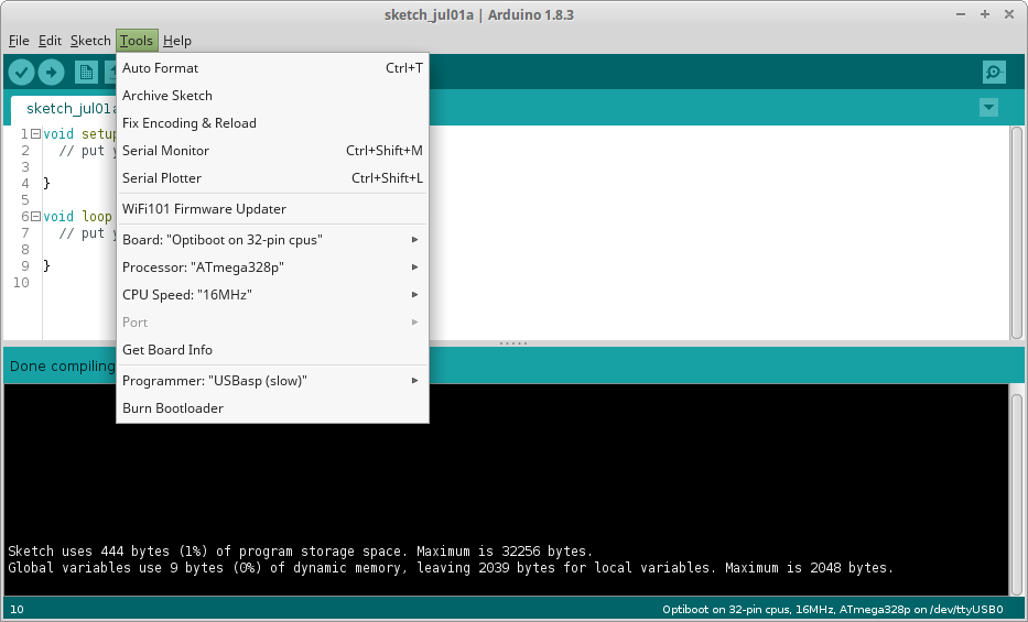 Gambar 10. Pengaturan konfigurasi untuk pengisian bootloader
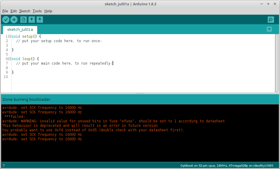 Gambar 11.