Sebelumnya saya sudah membuat catatan tentang Arduino shield yang berisi empat relay. Di pasaran lokal, pembeli perlu cermat karena rating relay bisa jadi tidak sesuai dengan aplikasi yang direncanakan.
 Gambar 1.
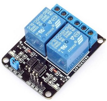
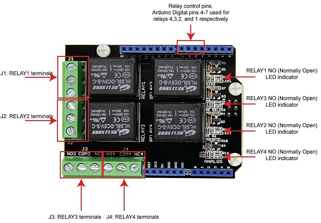
Kali ini adalah catatan tentang papan relay (relai) seperti pada Gambar 1. Rating relai dapat dibaca di bagian atas masing-masing relai, untuk kemudian bisa dibandingkan dengan datasheet yang sesuai. Yang sangat penting diperhatikan adalah mengenai single-line header yang tampak sebagai selection jumper pada bagian kiri dari Gambar 1. Di sana tertulis JD-VCC, VCC dan GND. Lebih detail bisa dilihat pada Gambar 2.
 Gambar 2. [sumber]
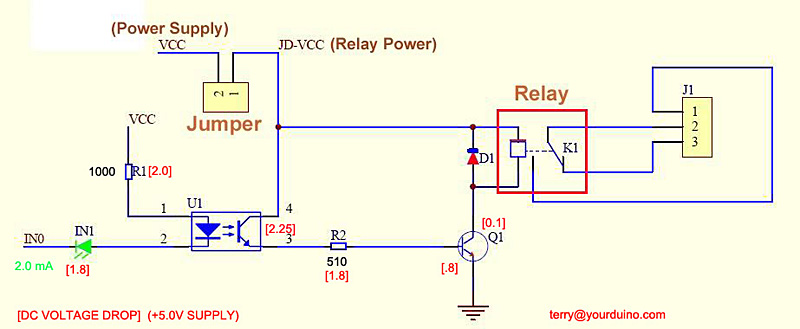
Posisi jumper secara default dari awal adalah terhubung antara JD-VCC dengan VCC. Konfigurasi ini berarti catu daya untuk optocoupler, transistor BJT dan relai berasal dari catu daya VCC yang sama untuk pemberian sinyal ke optocouler. Perlu berhati-hati VCC pada header ini secara elektris terhubung dengan header VCC untuk masukkan, bisa dilihat langsung pada bagian bawah PCB. Begitu pula GND pada header yang sama.
 Gambar 3. [sumber]
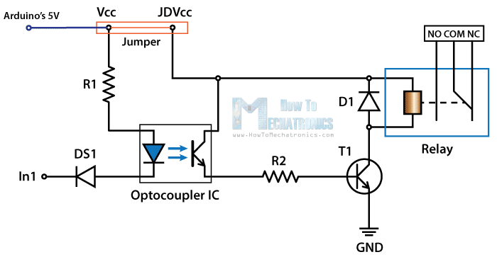
Gambar 3 menyampaikan informasi yang sama dengan cara yang berbeda. Di sini bagian GND pada header dihilangkan sehingga jelas bahwa jumper itu bukanlah selector-jumper. Jangan menghubungkan antara VCC dengan GND! Fungsi pin GND pada header itu adalah untuk penyambungan ke sumber catu daya lain. Dua kabel yang perlu disambungkan adalah JD-VCC dan GND, sehingga GND dari catu daya ini akan terhubung dengan GND pada papan pengendali (mikrokontroler seperti ATmega328P atau sistem Arduino).
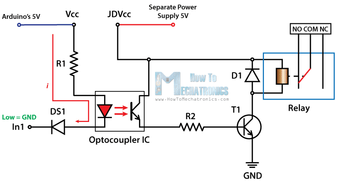
Dari situs http://howtomechatronics.com, bisa juga dilihat gambar yang memberi keterangan tentang sambungan daya.
 Gambar 4. Menggunakan catu daya Arduino [sumber]
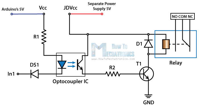 Gambar 5. Menggunakan catu daya terpisah (sambungkan juga GND) [sumber]
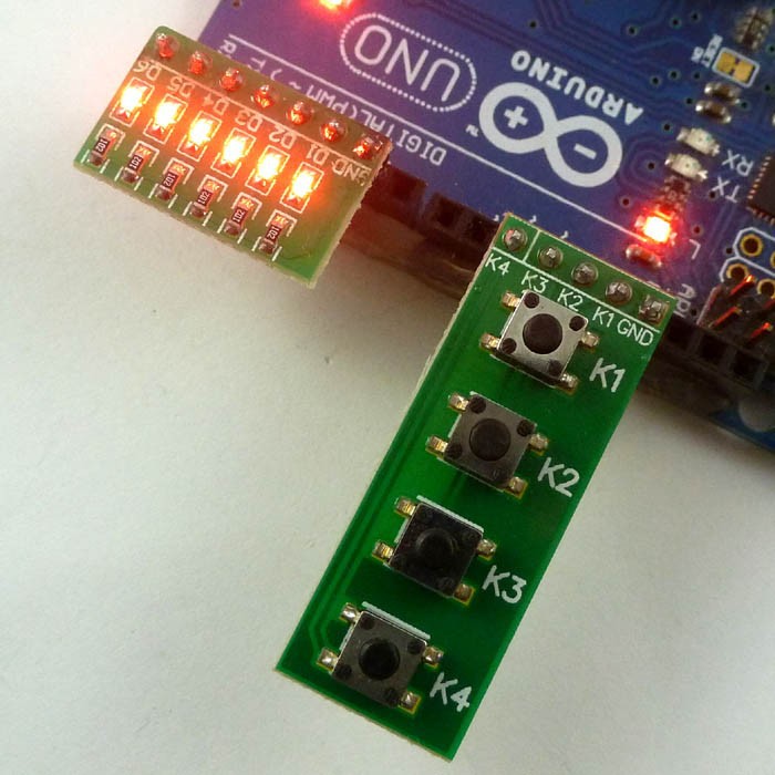
 Gambar 6. Papan sistem menggunakan active-low [sumber]
Keterangan yang lebih baik bisa diperoleh langsung dari situs aslinya di link ini: howtomechatronics.com .
Berdasar pengetahuan yang diperoleh dari Gambar 6, kita bisa melakukan pengaturan pada kode progam sehingga penggunaan relai tidak terganggu dengan kode program yang janggal atau tidak natural.
const uint8_t IND_LED_PIN = 1;
#define BLINK_DELAY 500
#define RELAY_ON LOW
#define RELAY_OFF HIGH
#define IN1 3
#define IN2 4


void safeRelayInit(void)
{
  digitalWrite(IN1, HIGH);
  digitalWrite(IN2, HIGH);
  delay(100);
  pinMode(IN1, OUTPUT);
  pinMode(IN2, OUTPUT);
}


void relayTest001(void)
{
  digitalWrite(IN1, LOW);
  delay(2000);
  digitalWrite(IN1, HIGH);
  delay(2000);

  digitalWrite(IN2, LOW);
  delay(2000);
  digitalWrite(IN2, HIGH);
  delay(2000);
}

void relayTest002(void)
{
  digitalWrite(IN1, RELAY_ON);
  delay(1000);
  digitalWrite(IN1, RELAY_OFF);
  delay(1000);

  digitalWrite(IN2, RELAY_ON);
  delay(1000);
  digitalWrite(IN2, RELAY_OFF);
  delay(1000);
}

void setup(void)
{
  safeRelayInit();
  delay(10);


  pinMode(IND_LED_PIN, OUTPUT);
  digitalWrite(IND_LED_PIN, LOW);


  delay(1000);
  digitalWrite(IND_LED_PIN, HIGH);
  delay(1000);

  // relayTest001();

  for (int i = 0; i < 2; ++i)
  {
    /* code */
    relayTest002();
  }


  digitalWrite(IND_LED_PIN, LOW);

}


void loop(void)
{

}
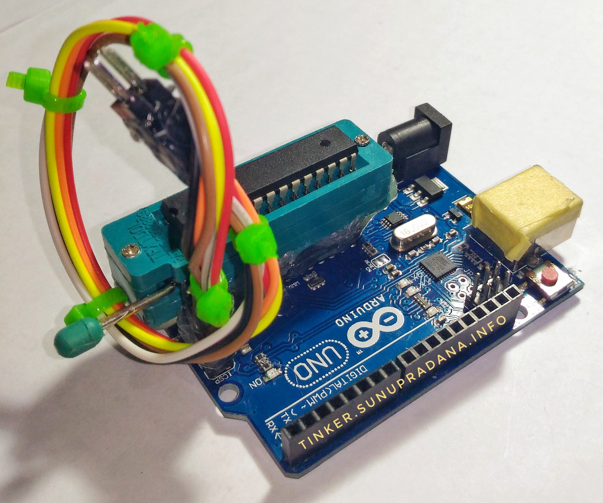
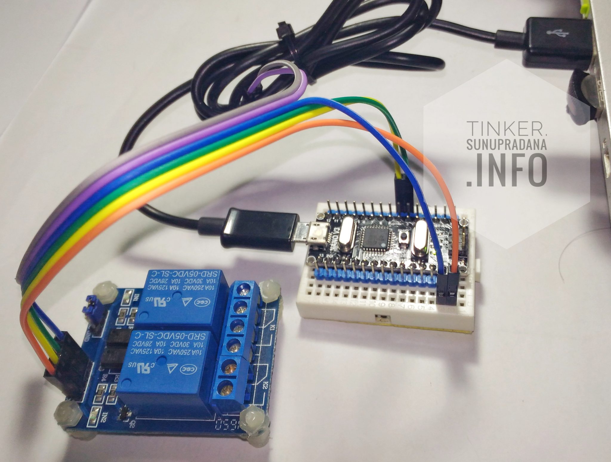 Gambar 7. Papan SRD-05VDC-SL-C
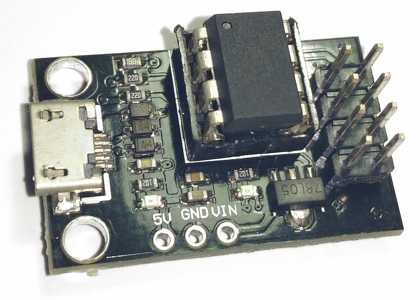
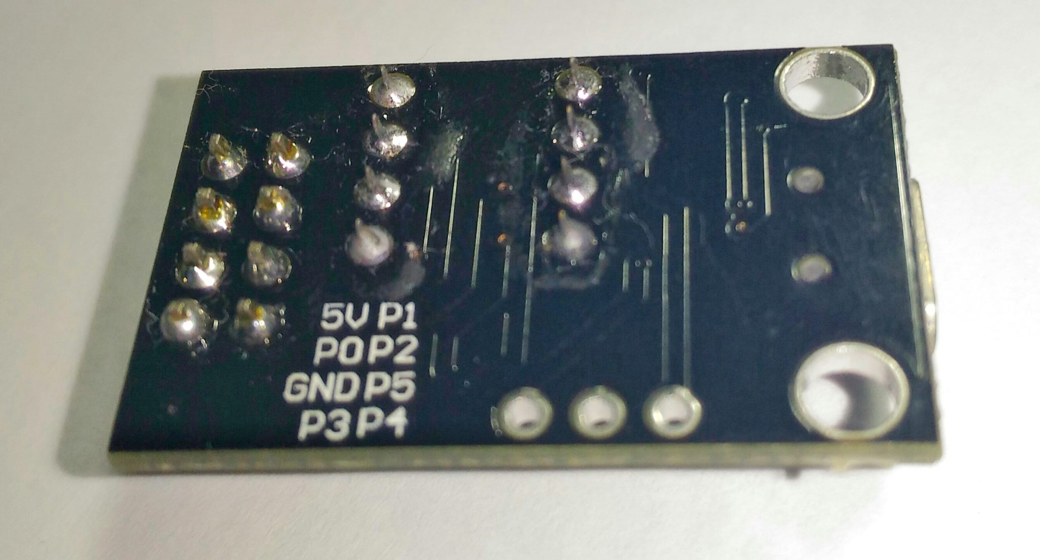
 Gambar 8.
SONGLE SRD relay by Sunu Pradana on Scribd
 Gambar 2. [
 Gambar 3. [
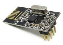 Gambar 1. nRF24L01 [
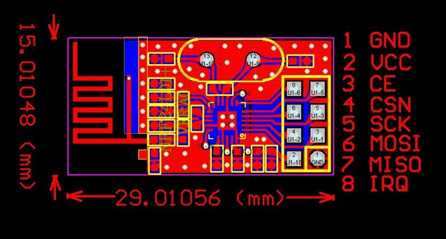 Gambar 2. nRF24L01 [
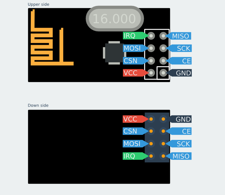 Gambar 3. nRF24L01 [
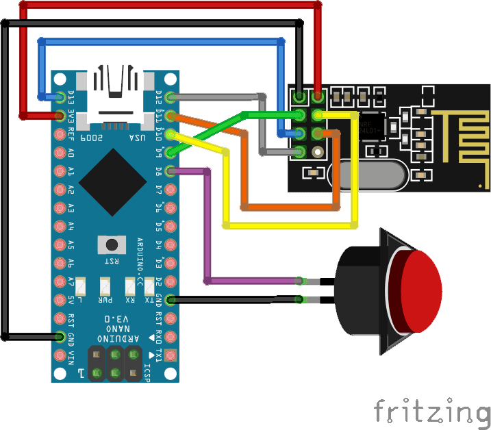
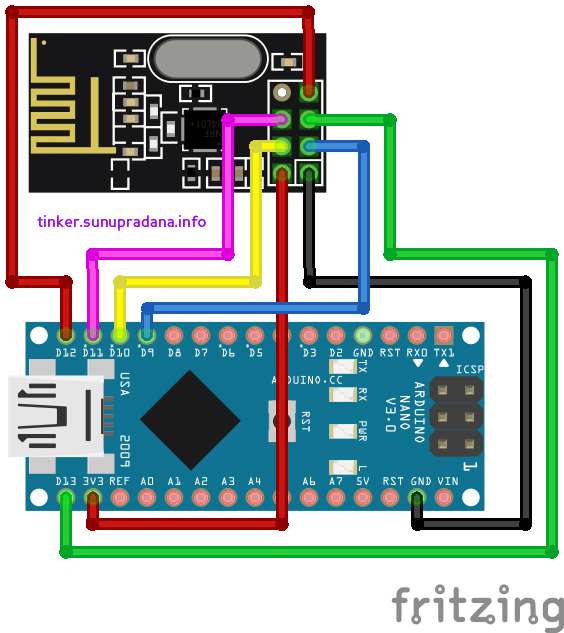
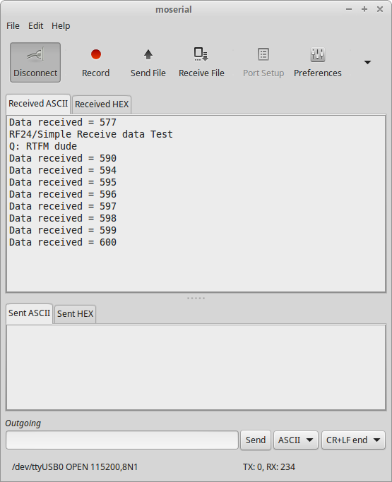
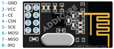 Gambar 4. nRF24L01 [
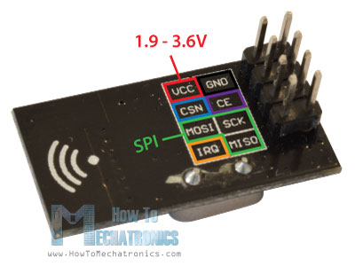 Gambar 5. [
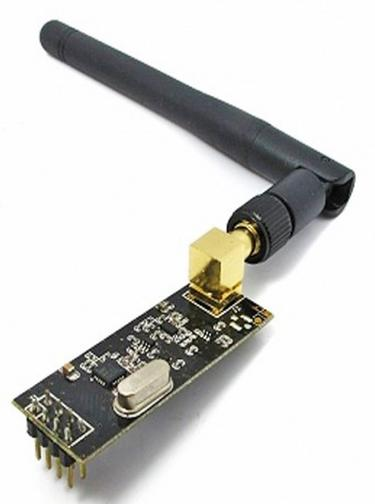 Gambar 6. [
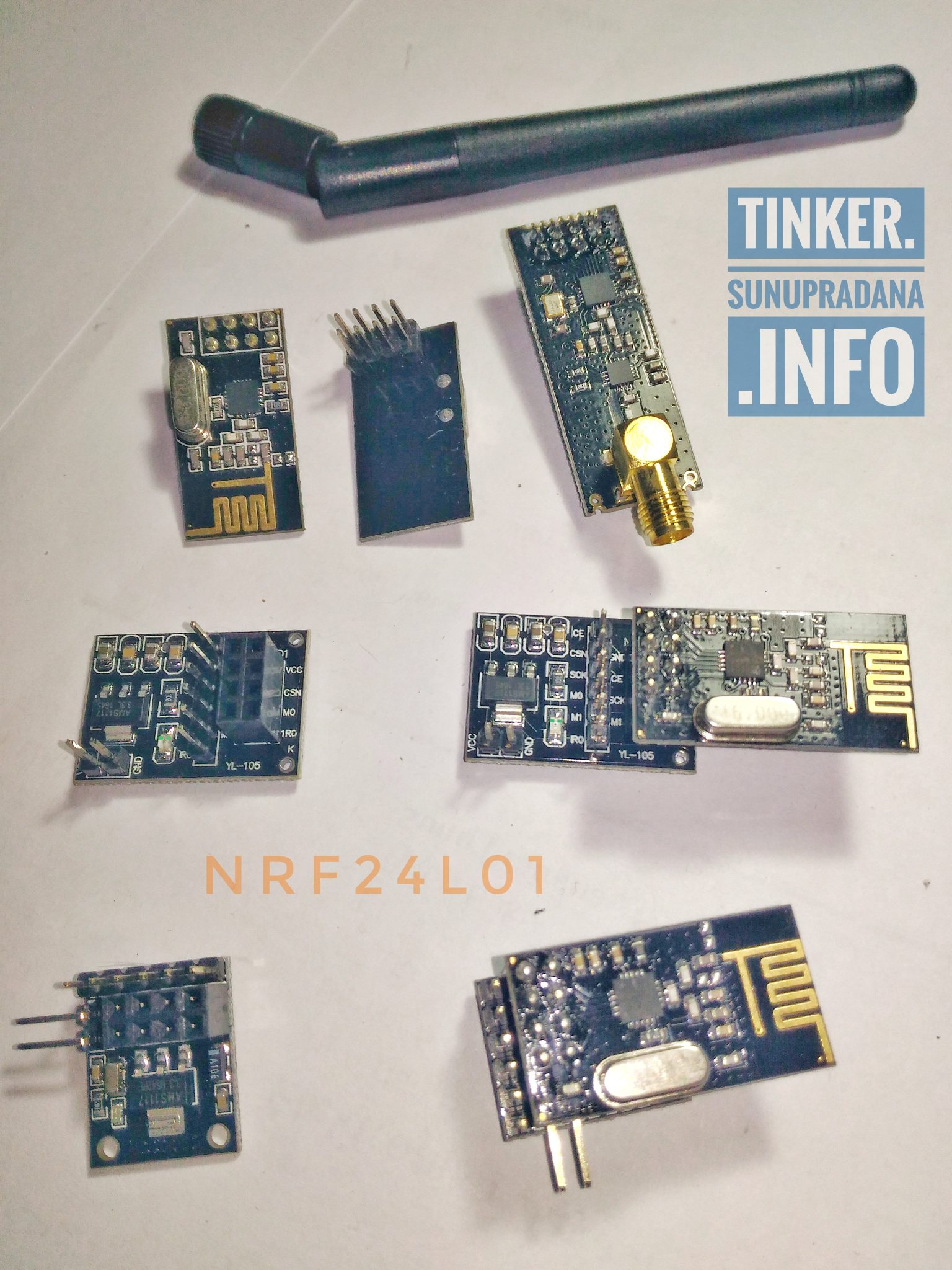
 Gambar 8. [
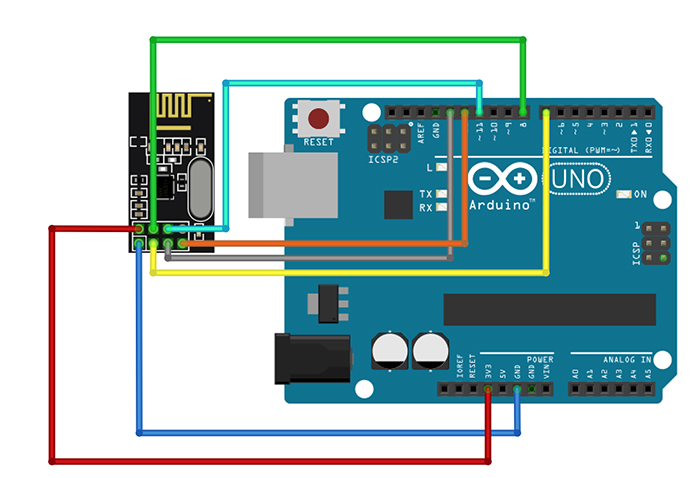 Gambar 9. [
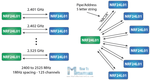 Gambar 10. [
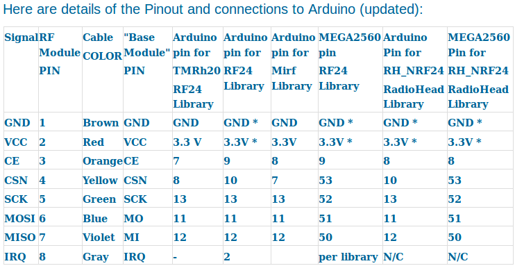
 Gambar 12.
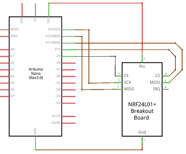 Gambar 13.
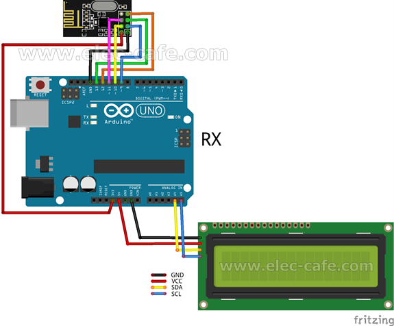 Gambar 14. [
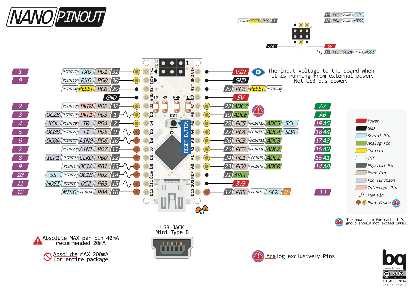

 Gambar 17.
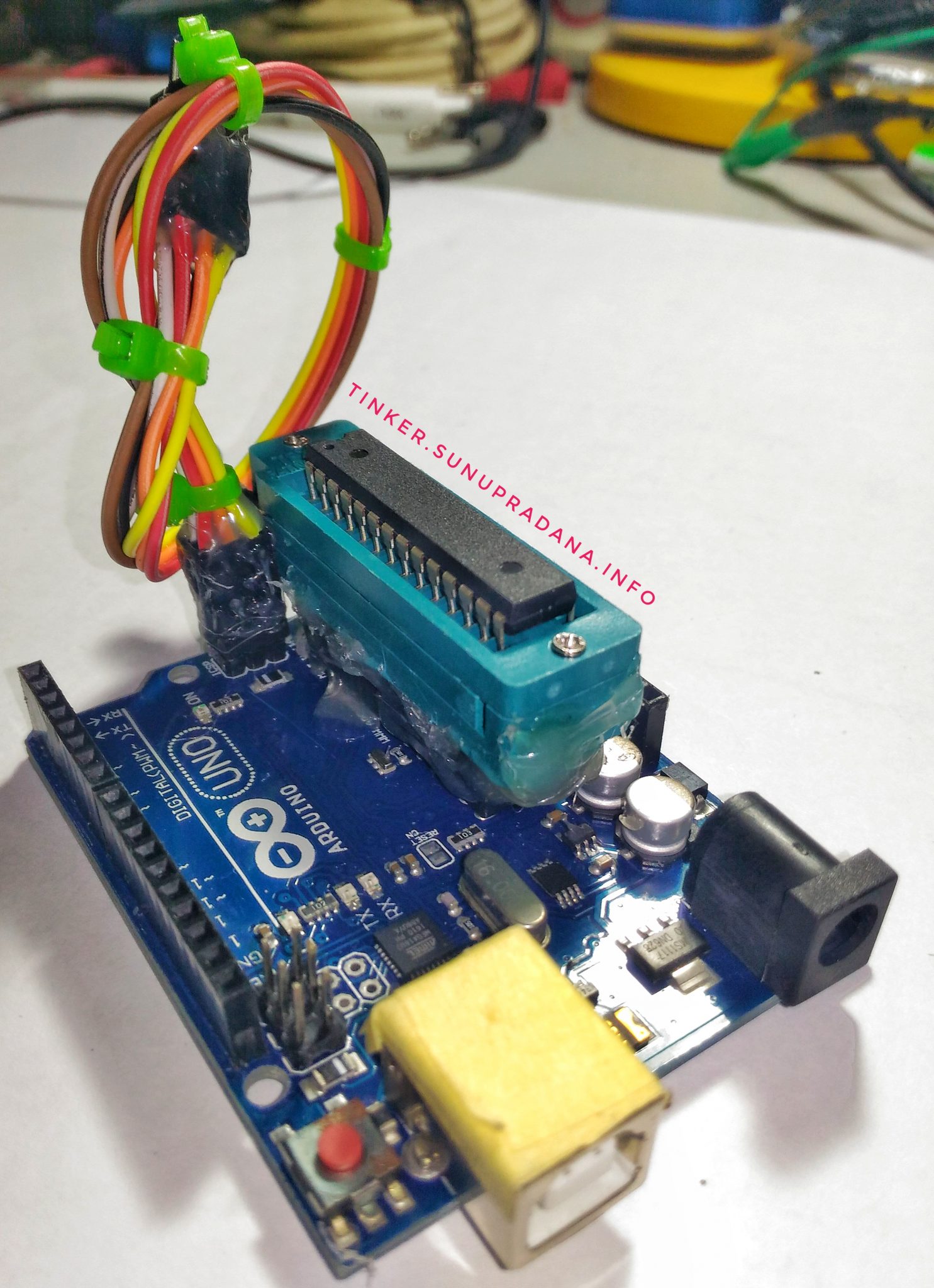
 Gambar 3.
 Gambar 7.
 Gambar 8.
 Gambar 9.
 Gambar 10.
 Gambar 11.
 Gambar 12.

 Gambar 1.
 Gambar 2. [
 Gambar 3. [
 Gambar 4. [
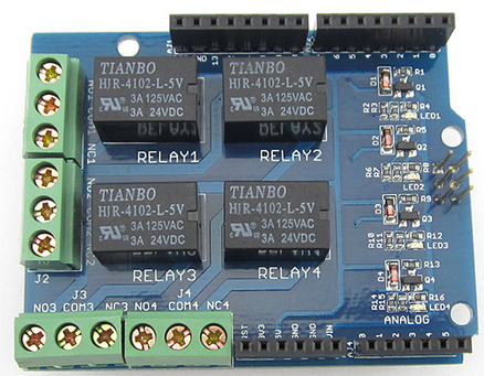
 Gambar 2. Seeed Arduino Relay Shield V2.0 [
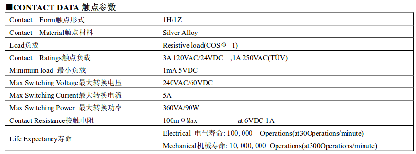 Gambar 3. [
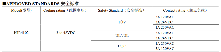 Gambar 4. [


 Gambar 6. [
 Gambar 12.
 Gambar 13.
 Gambar 14.
 Gambar 15.
 Gambar 16.
 Gambar 17.
 Gambar 18.
 Gambar 19.
 Gambar 20.
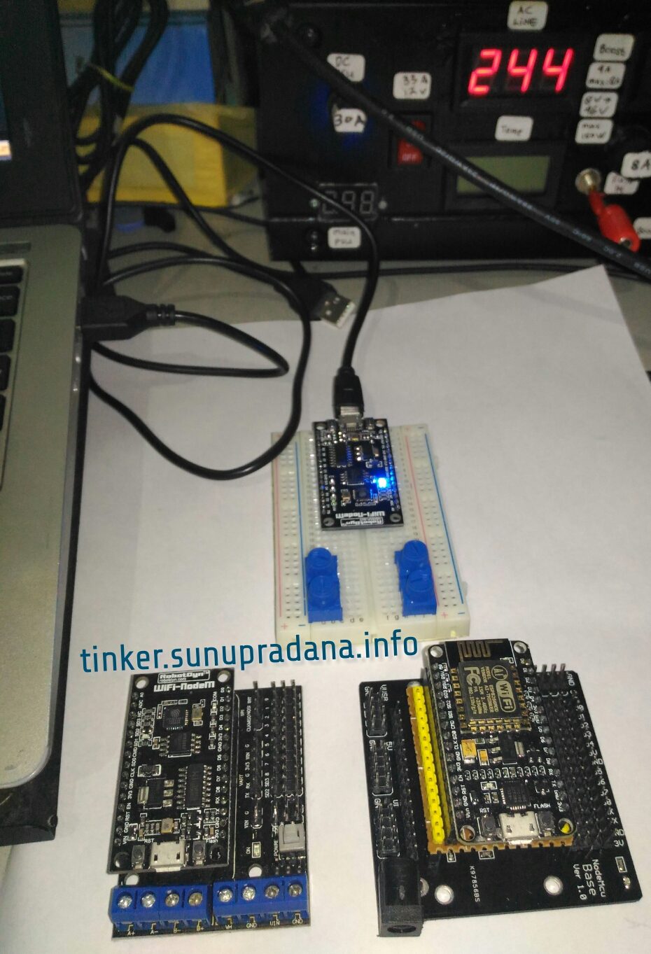
 Gambar 1. NodeMCU [
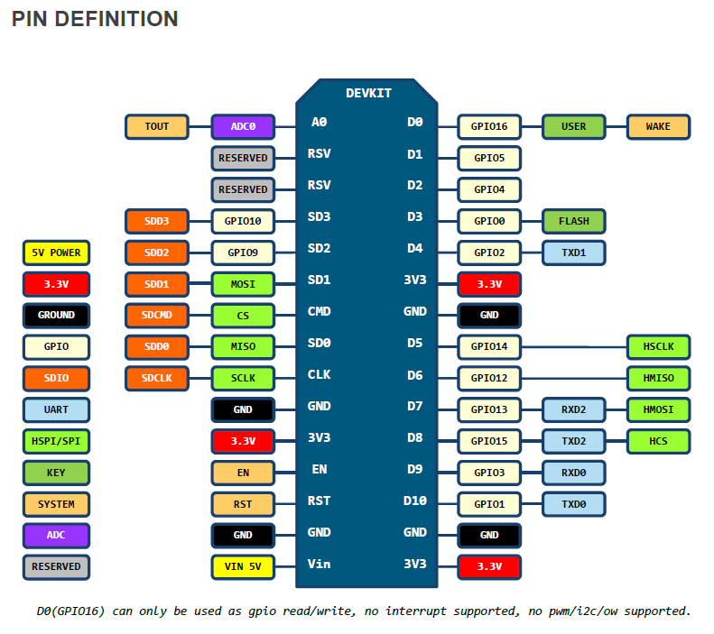 Gambar 2. [
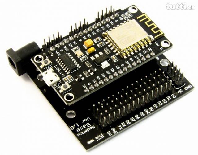 Gambar 3. NodeMCU + Base yang tidak memerlukan tambahan adapter [
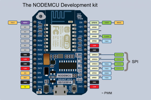 Gambar 4. NodeMCU v0.9 pinout [
 Gambar 5.
 Gambar 6.
 Gambar 7.
 Gambar 8.
 Gambar 9.
 Gambar 10.
 Gambar 11.
 Gambar 13.