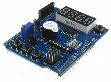
Papan fungsi shield untuk uji komponen dengan empat 7-segment.
 Gambar 1.
Gambar 2. [sumber]
 Gambar 3. [sumber]
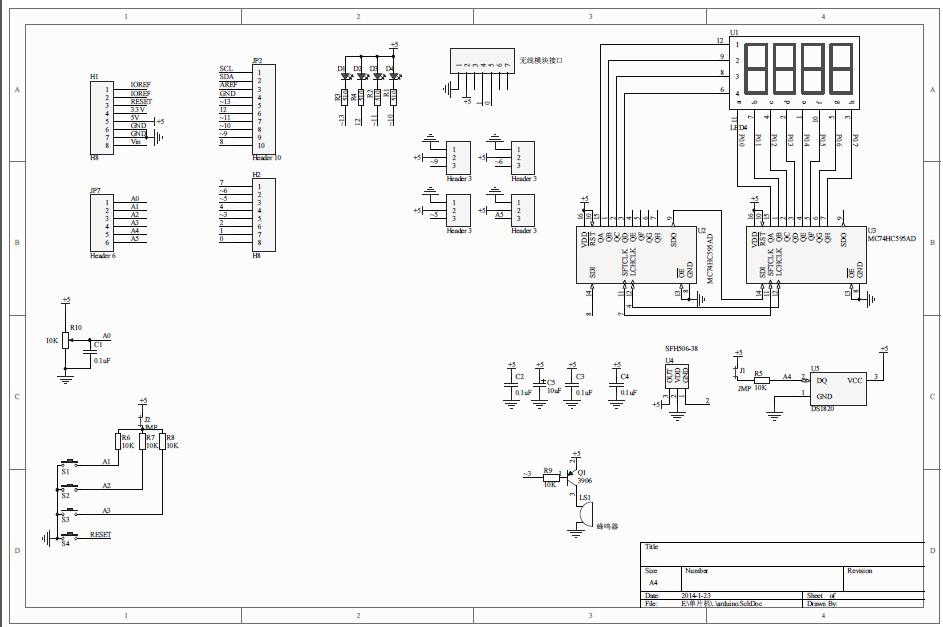
J1 is used for a 10 k pull up resistor to pin 2 of U5 (to connect a DS1820 temperature sensor [not included with the shield]) (Arduino Pin A4 ?) {Location C4 in the picture}
J2 is needed if you want to use the switches S1 S2 and S3 (connected to A1 A2 and A3 of the Arduino. {Location C1 in picture}
A SFH506-38 IR receiver (Pin D2) {Location C3 in picture} is also not included with this shield and can be connected to U4
I expect the 7 pin header {Location B/C1 in picture} with the Chinese characters is the header 7 pin header marked on the shield with “APC220 Bluetooth Voice Recognition Module”. (Pin D0 and D1 ?)
Pin D5 D6 D9 and A5 are accessible by 4 3 pin header connectors next to +5V and GND
D3 is connected to the Buzzer using a transistor! {Location D3 in picture}
The 4 * 7segement displays are connected using two MC74HC595AD shift registers
D4 7segment Latch
D7 7segment CLK
D8 7segment DataD10 Led4 {Location A2 in picture}
D11 Led3
D12 Led2
D13 Led1A0 Pot1 (potentiometer) {Location B/C1 in picture}
A1 Button1 {Location C/D1 in picture}
A2 Button2
A3 Button3
- All LEDs blinking
int led1 = 13; int led2 = 12; int led3 = 11; int led4 = 10; void setup() { // initialize the digital pin as an output. pinMode(led1, OUTPUT); pinMode(led2, OUTPUT); pinMode(led3, OUTPUT); pinMode(led4, OUTPUT); } void loop() { digitalWrite(led1, HIGH); digitalWrite(led2, HIGH); digitalWrite(led3, HIGH); digitalWrite(led4, HIGH); delay(1000); digitalWrite(led1, LOW); digitalWrite(led2, LOW); digitalWrite(led3, LOW); digitalWrite(led4, LOW); delay(1000); } - Switches example
const byte LED[] = {13,12,11,10}; #define BUTTON1 A1 #define BUTTON2 A2 void setup() { // initialize the digital pin as an output. /* Set each pin to outputs */ pinMode(LED[0], OUTPUT); pinMode(LED[1], OUTPUT); pinMode(LED[2], OUTPUT); pinMode(LED[3], OUTPUT); } void loop() { if(!digitalRead(BUTTON1)) { digitalWrite(LED[0], HIGH); digitalWrite(LED[1], HIGH); digitalWrite(LED[2], HIGH); digitalWrite(LED[3], HIGH); } if(!digitalRead(BUTTON2)) { digitalWrite(LED[0], LOW); digitalWrite(LED[1], LOW); digitalWrite(LED[2], LOW); digitalWrite(LED[3], LOW); } } - Potentiometer 1
#define Pot1 0 void setup() { Serial.begin(9600); } /* Main Program */ void loop() { Serial.print("Potentiometer reading: "); Serial.println(analogRead(Pot1)); /* Wait 0.5 seconds before reading again */ delay(500); } - Pot and led
const byte LED[] = {13,12,11,10}; #define Pot1 0 void setup() { Serial.begin(9600); // initialize the digital pin as an output. /* Set each pin to outputs */ pinMode(LED[0], OUTPUT); pinMode(LED[1], OUTPUT); pinMode(LED[2], OUTPUT); pinMode(LED[3], OUTPUT); } /* Main Program */ void loop() { int PotValue; //Serial.print("Potentiometer reading: "); PotValue = analogRead(Pot1); /* Wait 0.5 seconds before reading again */ if(PotValue < 400) { digitalWrite(LED[0], LOW); digitalWrite(LED[1], LOW); digitalWrite(LED[2], LOW); digitalWrite(LED[3], LOW); Serial.print("Potentiometer: "); Serial.println(PotValue); } else { digitalWrite(LED[0], HIGH); digitalWrite(LED[1], HIGH); digitalWrite(LED[2], HIGH); digitalWrite(LED[3], HIGH); Serial.print("Potentiometer: "); Serial.println(PotValue); } delay(500); } - Segment display
/* Define shift register pins used for seven segment display */ #define LATCH_DIO 4 #define CLK_DIO 7 #define DATA_DIO 8 /* Segment byte maps for numbers 0 to 9 */ const byte SEGMENT_MAP[] = {0xC0,0xF9,0xA4,0xB0,0x99,0x92,0x82,0xF8,0X80,0X90}; /* Byte maps to select digit 1 to 4 */ const byte SEGMENT_SELECT[] = {0xF1,0xF2,0xF4,0xF8}; void setup () { /* Set DIO pins to outputs */ pinMode(LATCH_DIO,OUTPUT); pinMode(CLK_DIO,OUTPUT); pinMode(DATA_DIO,OUTPUT); } /* Main program */ void loop() { /* Update the display with the current counter value */ WriteNumberToSegment(0 , 0); WriteNumberToSegment(1 , 1); WriteNumberToSegment(2 , 2); WriteNumberToSegment(3 , 3); } /* Write a decimal number between 0 and 9 to one of the 4 digits of the display */ void WriteNumberToSegment(byte Segment, byte Value) { digitalWrite(LATCH_DIO,LOW); shiftOut(DATA_DIO, CLK_DIO, MSBFIRST, SEGMENT_MAP[Value]); shiftOut(DATA_DIO, CLK_DIO, MSBFIRST, SEGMENT_SELECT[Segment] ); digitalWrite(LATCH_DIO,HIGH); } - Read pot and display value on display
/* Define shift register pins used for seven segment display */ #define LATCH_DIO 4 #define CLK_DIO 7 #define DATA_DIO 8 #define Pot1 0 /* Segment byte maps for numbers 0 to 9 */ const byte SEGMENT_MAP[] = {0xC0,0xF9,0xA4,0xB0,0x99,0x92,0x82,0xF8,0X80,0X90}; /* Byte maps to select digit 1 to 4 */ const byte SEGMENT_SELECT[] = {0xF1,0xF2,0xF4,0xF8}; void setup () { Serial.begin(9600); /* Set DIO pins to outputs */ pinMode(LATCH_DIO,OUTPUT); pinMode(CLK_DIO,OUTPUT); pinMode(DATA_DIO,OUTPUT); } /* Main program */ void loop() { int PotValue; PotValue = analogRead(Pot1); Serial.print("Potentiometer: "); Serial.println(PotValue); /* Update the display with the current counter value */ WriteNumberToSegment(0 , PotValue / 1000); WriteNumberToSegment(1 , (PotValue / 100) % 10); WriteNumberToSegment(2 , (PotValue / 10) % 10); WriteNumberToSegment(3 , PotValue % 10); } /* Write a decimal number between 0 and 9 to one of the 4 digits of the display */ void WriteNumberToSegment(byte Segment, byte Value) { digitalWrite(LATCH_DIO,LOW); shiftOut(DATA_DIO, CLK_DIO, MSBFIRST, SEGMENT_MAP[Value]); shiftOut(DATA_DIO, CLK_DIO, MSBFIRST, SEGMENT_SELECT[Segment] ); digitalWrite(LATCH_DIO,HIGH); } - Read pot and display value on display (modifikasi untuk meratakan tingkat terang tampilan)
/* Define shift register pins used for seven segment display */
#define LATCH_DIO 4
#define CLK_DIO 7
#define DATA_DIO 8
#define Pot1 0
/* Segment byte maps for numbers 0 to 9 */
const byte SEGMENT_MAP[] = {0xC0,0xF9,0xA4,0xB0,0x99,0x92,0x82,0xF8,0X80,0X90};
/* Byte maps to select digit 1 to 4 */
const byte SEGMENT_SELECT[] = {0xF1,0xF2,0xF4,0xF8};
void setup ()
{
  Serial.begin(9600);
  /* Set DIO pins to outputs */
  pinMode(LATCH_DIO,OUTPUT);
  pinMode(CLK_DIO,OUTPUT);
  pinMode(DATA_DIO,OUTPUT);
}
/* Main program */
void loop()
{
  int PotValue;
  PotValue = analogRead(Pot1);
  Serial.print("Potentiometer: ");
  Serial.println(PotValue);
  /* Update the display with the current counter value */
  WriteNumberToSegment(0 , PotValue / 1000);
  delay(5);
  WriteNumberToSegment(1 , (PotValue / 100) % 10);
  delay(5);
  WriteNumberToSegment(2 , (PotValue / 10) % 10);
  delay(5);
  WriteNumberToSegment(3 , PotValue % 10);
//  delay(4);
}
/* Write a decimal number between 0 and 9 to one of the 4 digits of the display */
void WriteNumberToSegment(byte Segment, byte Value)
{
  digitalWrite(LATCH_DIO,LOW);
  shiftOut(DATA_DIO, CLK_DIO, MSBFIRST, SEGMENT_MAP[Value]);
  shiftOut(DATA_DIO, CLK_DIO, MSBFIRST, SEGMENT_SELECT[Segment] );
  digitalWrite(LATCH_DIO,HIGH);
}
Sumber lain:
Hackatronics: Using an Arduino Multi-function Shield